3 Mounting and Commissioning
278
7UM61 Manual
C53000-G1176-C127-3
Together with the voltage divider R
T
500 V/100 V this corresponds to a displacement
voltage at the input of the device of:
The pickup value U0> for the neutral displacement voltage should amount to at least
twice the value of this interference voltage.
Example:
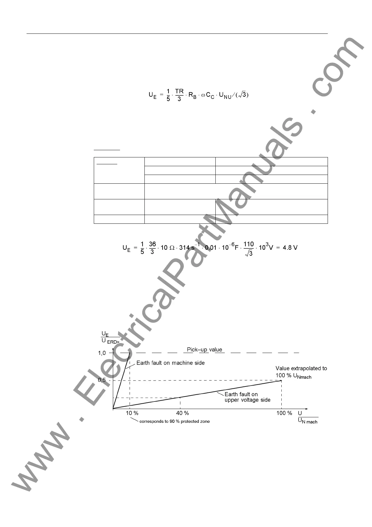
10 V has been chosen as the setting value for 5002 in address U0> which corre-
sponds to a protective zone of 90% (see the following Figure).
Note: For use as a neutral transformer the voltage transformation ratio TR instead of
TR/3 should be used. As this has only one winding, the result is the same.
Figure 3-18 Displacement voltage during earth faults
Network
U
NU
= 110 kV
f
Nom
= 50 Hz
C
C
= 0.01 µF
Voltage transform-
er
10 kV / 0.1 kV
Earthing transform-
er
TR = 36
Loading resistance R
B
= 10 Ω
www . ElectricalPartManuals . com

 Loading...


