3.3 Commissioning
277
7UM61 Manual
C53000-G1176-C127-3
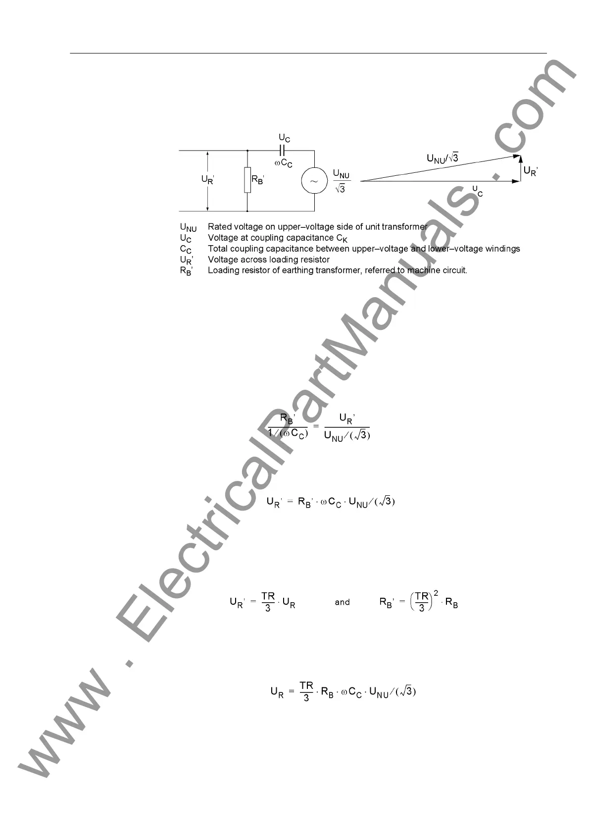
Calculation of Pro-
tected Zone
Coupling capacitance C
C
and loading resistor R
B
represent a voltage divider, whereby
R
B
is the resistance R
B
referred to the machine terminal circuit.
Figure 3-17 Equivalent Diagram and Vector Diagram
Equivalent circuit and vector diagram Since the reactance of the coupling capacitance
is much larger than the referred resistance of the loading resistor RB', U
C
≈ U
NO
/√3
can be set (see also vector diagram Figure 3-17), where U
NO
/√3 is the neutral dis-
placement voltage with a full displacement of the network voltage starpoint. The fol-
lowing applies:
With the voltage transformation ratio TR of the earthing transformer:
we obtain:
www . ElectricalPartManuals . com

 Loading...


