4.24 Auxiliary Functions
341
7UM61 Manual
C53000-G1176-C127-3
Trip Circuit Monitoring
Commissioning Aids
Clock
User Defined Functions (CFC)
Number of monitorable circuits 1
with one or two binary inputs
Phase Rotation Field Check
Operational measured values
Switching device test
Creation of a Test Measurement Report
Time synchronization DCF 77
IRIG B-Signal (telegram format IRIG-B000)
Binary Input
Communication
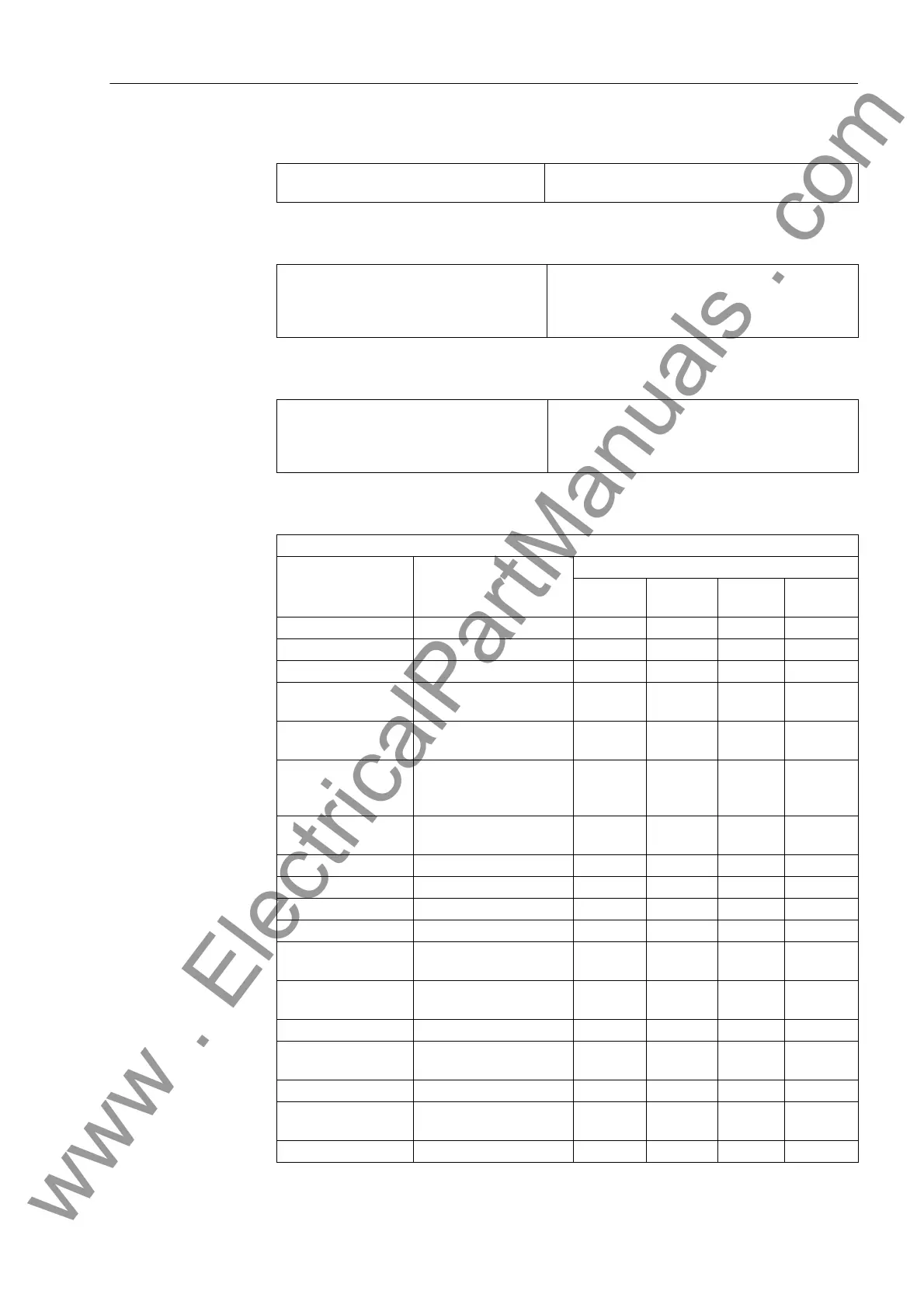
Function Modules and Possible Allocation to Task Levels
Function Module Explanation Sequence Level
MW_
BEARB
PLC1_
BEARB
PLC1_
BEARB
SFS_
BEARB
ABSVALUE Amplitude formation X — — —
ADD Addition X X X X
AND AND Gate — X X X
BOOL_TO_CO Boolean to Command
(Conversion)
—XX—
BOOL_TO_DI Boolean to Double Point
Indication (Conversion)
—XXX
BOOL_TO_IC Boolean to Internal
Single Point Indication
(Conversion)
—XXX
BUILD_DI Create a Double Point In-
dication
—XXX
CMD_CHAIN Switching sequence — X X —
CMD_INF Command Information — — — X
CONNECT Connection — X X X
D_FF D–Flipflop — X X X
D_FF_MEMO Status Memory for
Restart
—XXX
DI_TO_BOOL Double Point Indication
to Boolean (Conversion)
—XXX
DIV Division X — — —
DM_DECODE Decode Double Point In-
dication
XXXX
DYN_OR Dynamic OR gate X X X X
LIVE_ZERO Live–zero Monitoring,
Nonlinear Characteristic
X———
LONG_TIMER Timer (max. 1193 h) X X X X
www . ElectricalPartManuals . com

 Loading...


