4 Technical Data
342
7UM61 Manual
C53000-G1176-C127-3
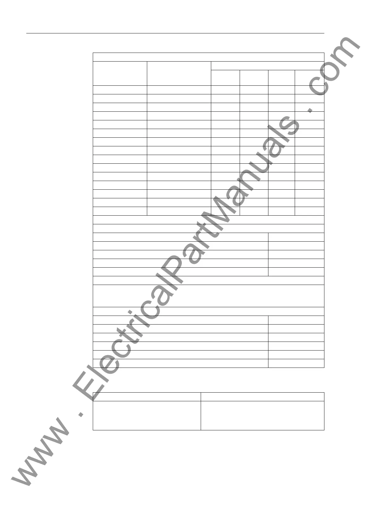
Group Switchover of the Function Parameters
LOOP Signal Feedback — X — —
LOWER_SETPOINT Limit value undershoot X — — —
MUL Multiplication X — — —
NAND NAND Gate — X X X
NEG Negator — X X X
NOR NORNOR Gate — X X X
OR OR Gate — X X X
RS_FF RS–Flipflop — X X X
SQUARE_ROOT Square Root Extractor X — — —
SR_FF SR–Flipflop — X X X
SUB Subtraction X — — —
TIMER Universal Timer — X X —
UPPER_SETPOINT Upper Limit X — — —
X_OR XOR Gate — X X X
ZERO_POINT Zero Suppression X — — —
Maximum number of TICKS in the task levels
Sequence Level Limit in TICKS
MW_BEARB (Measured value processing) 2 500
PLC1_BEARB (slow PLC processing) 250
PLC_BEARB (fast PLC processing) 130
SFS_BEARB (interlocking) 2 100
The following table shows the number of required TICKS for the individual elements of a CFC
chart. A generic module is one where the number of inputs can be changed; typical are the
logic functions AND, NAND, OR, NOR.
Processing times in TICKS required by the individual elements
Individual Element Number of TICKS
Module, basic requirement 5
each input from the 3rd additional input for generic modules 1
Connection to an input margin 6
Combination with output signal border 7
additionally for each chart 1
Function Modules and Possible Allocation to Task Levels
Function Module Explanation Sequence Level
MW_
BEARB
PLC1_
BEARB
PLC1_
BEARB
SFS_
BEARB
Number of Available Setting Groups 2 (parameter group A and B)
Switchover can be performed using the keypad
DIGSI
®
4 using the operating interface
with protocol via system interface
Binary Input
www . ElectricalPartManuals . com

 Loading...


