Connection
8.1 Warning notice
SIRIUS - SIRIUS 3RT Contactors/Contactor assemblies
228 Manual, 09/2017, A5E03656507120A/RS-AE/006
Terminal designations of the auxiliary contacts
The terminal designations as per EN 50012 apply to size S00 contactors with an integrated
auxiliary (NO) contact. Auxiliary contacts are fitted and arranged on size S0 contactors
(integrated in the basic device) in accordance with the terminal designations contained in
DIN EN 50012.
Additionally, for sizes S00 and S0, complete devices with permanently mounted auxiliary
switch blocks (2 NO contacts + 2 NC contacts in accordance with DIN EN 50012) are
available.
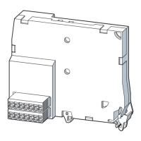
Size S00 to S3 contactors feature a coil terminal on the front. An adapter (3RT2926-4R./. coil
terminal module) can be used to move the coil terminal up or down on size S0 / S2 / S3
contactors (compatible with 3RT102 / 3RT103).
Can be found in the chapter ...
About the coil terminal module and how to mount
it on a 3RT20 contactor (size S0)
Coil terminal module (Page 343)
The devices with screw connections have the following features:
● All connections are equipped with captive screws
● All connection points are supplied open
● Screwdriver guides enable the use of machine screwdrivers
● On size S00, all connecting screws for main and auxiliary circuits have a uniform screw
size (POZIDRIV cross-tip screw size 2) and thus require the same tightening torque.
● On all sizes (S00 to S12), the connecting screws for the auxiliary conductor connections
are identical (POZIDRIV size 2, no bit replacement, uniform tightening torque)
Devices with spring-loaded connection system have the following properties:
● The contactors are recommended when powerful shaking or vibration is to be expected at
the location of use.
● The terminals are suitable for 2-conductor connection.
● All connections can be accessed from the front and are clearly arranged.
● A maximum of 2 conductors with a cross-section of 0.25 mm
2
to max. 2.5 mm
2
can be
used at each connection point.

 Loading...
