Accessories
9.3 Auxiliary switch blocks
SIRIUS - SIRIUS 3RT Contactors/Contactor assemblies
290 Manual, 09/2017, A5E03656507120A/RS-AE/006
Configuration
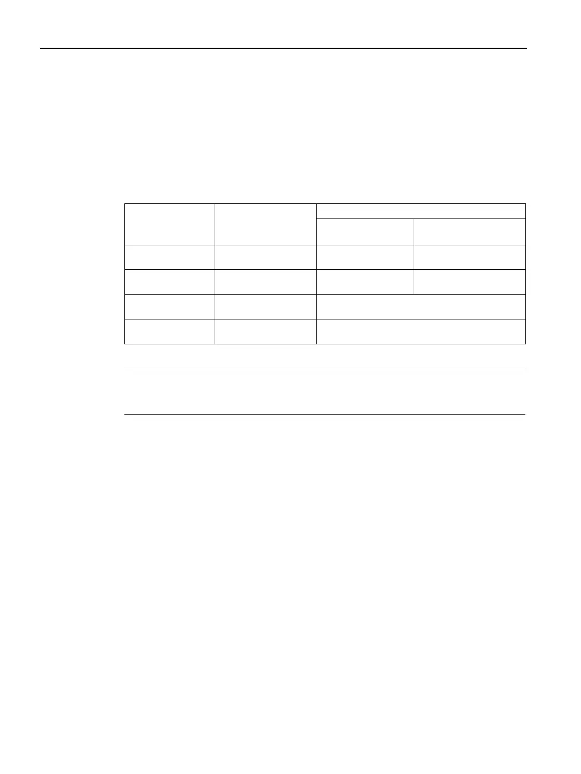
Maximum number of auxiliary switch blocks
The maximum number of auxiliary switch blocks which can be attached is determined by
technical constraints and by the applicable standard.
The tables below show the maximum number of auxiliary contacts that can be mounted on
3RT1 power contactors.
In the lower operating range
3RT1...-.A
3RT10 / 3RT14 air-
8, of which max. 4 NC
9, of which max. 6 NC
3RT12 vacuum
8, of which max. 4 NC
8, of which max. 6 NC
3RT1...-.N electronic Air-break contactors /
8, of which max. 4 NC contacts
with RLT 3RT1...-
3RT10 / 3RT14 air-
8, of which max. 4 NC contacts
-pole laterally mountable auxiliary switch blocks are used, one block must be
attached on the right and one on the left for reasons of symmetry.
Note about fitting auxiliary switches
When using the 3RA1954-2A mechanical interlock:
● In the case of contactors with conventional / electronic operating mechanism 3RT1...-
.A/N:
an additional auxiliary switch block can be attached between the contactors
● In the case of contactors with remaining lifetime signal RLT 3RT1...-.P/Q:
the left mounted auxiliary contact block of the right contactor must be removed.