Configuration
6.3 Operating mechanism system / coil selection 3RT contactors and 3RH2 contactor relays
SIRIUS - SIRIUS 3RT Contactors/Contactor assemblies
Manual, 09/2017, A5E03656507120A/RS-AE/006
73
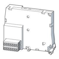
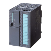
Solid-state operating mechanism for standard contactors
The solid-state operating mechanism
The solenoid coil is controlled by internal upstream control electronics. With the solid-state
operating mechanism, two different operating modes are possible. Version 1 is the classic
supply and control of the contactor via the control supply voltage applied to A1/A2. In the
case of version 2, only a supply voltage for the solenoid operating mechanism is applied at
A1/A2. The control can be applied to the additional terminals +/- as a 24 V DC signal. This
operating mode is suitable for controlling via higher-level semiconductor outputs (e.g. PLC).
Loss of the safety function with wiring of the control inputs.
Can cause death or serious injury.
For safety-related tripping, control via the control input PLC-IN is not permissible.
For safety-related applications, the contactor must be switched off via A1 / A2 or a
contactor with fail-safe control input must be used.
The contactors are equipped with wide-range operating mechanisms and can thus cover an
even wider range of control supply voltages, for example rated operating ranges (U
smin
-
U
smax
) of 96 V ... 127 V or 200 V ... 277 V. Both voltage types, AC as well as DC, are covered
by the same operating mechanism.
The operating range is 0.8 x U
s
min
- 1.1 x U
s
max
, for the example, this means: 0.8 x 200 V -
1.1 x 277 V.
Defined ON and OFF thresholds:
The control electronics monitor the applied control supply voltage for permissible lower limits
within which the contactors reliably switch.
● Switching on with control supply voltage 0.8 × U
s
min
● Switching off with control supply voltage ≤ 0.5 × U
s
min
The hysteresis in the switching thresholds prevents the main contacts from chattering and
thus prevents increased wear or welding when operated in weak, unstable networks.
The ON threshold prevents thermal overload of the coil if an excessively low control supply
voltage is applied.

 Loading...
