Accessories
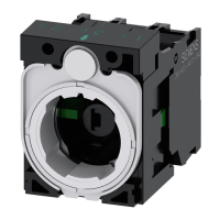
9.3 Auxiliary switch blocks
SIRIUS - SIRIUS 3RT Contactors/Contactor assemblies
Manual, 09/2017, A5E03656507120A/RS-AE/006
261
Table 9- 9 Auxiliary switch combination options (3RH2 contactor relay)
Size Number of integrated
auxiliary switches
Possible
versions
1-pole 4-pole 2-pole
S00 3RH21.-. 2 NO contacts and
2 NC contacts or 3 NO
contacts and 1 NC
contact or 4 NO
3 0 0 1
2)
3RH21..-.H..,
3RH21..-.J..,
3RH21..-.K..,
3RH21..-.M..,
3RH21..-.Q..,
3RH21..-.V..,
-- -- --
3RH24.. 2 NO contacts and
2 NC contacts or 3 NO
contacts and 1 NC
contact or 4 NO
3 -- -- --
Lateral auxiliary contacts without positively driven operation
2)
1 left and only 3RH2921-.DE11
Number of contacts in series (for control circuit / auxiliary circuit)
A large number of electromechanical contacts in series represents an increased potential for
functional faults. Since each contact point has a certain contact resistance, the resulting
cumulative voltage drop of the series-switched contacts can be sufficient to have a critical
effect on the functionality of certain loads or signal inputs.
In applications where it is necessary to scan a large number of contacts in series (e.g. in
enabling circuits or EMERGENCY STOP circuits), suitable measures must be taken to limit
the number of contacts switched directly in series. For example, the sequence of contacts
can also be distributed across several inputs for controllers, or the contacts can be multiplied
elsewhere.
It is not possible to provide a precise indication of the maximum permissible number of
series-switched contacts, as this depends on many factors, such as the current, voltage, or
other ambient conditions. Experience and feedback from the field have shown that, in
general, switching less than 10 contacts in series is a practicable approach.
In addition, the reliability of an individual contact can be increased by switching a second
contact in parallel.

 Loading...
