Home
Siemens
Control Unit
SIRIUS 3RT
Page 486
Siemens SIRIUS 3RT - Page 486
552 pages
Manual
Save Page as PDF
To Next Page
To Next Page
To Previous Page
To Previous Page
Loading...
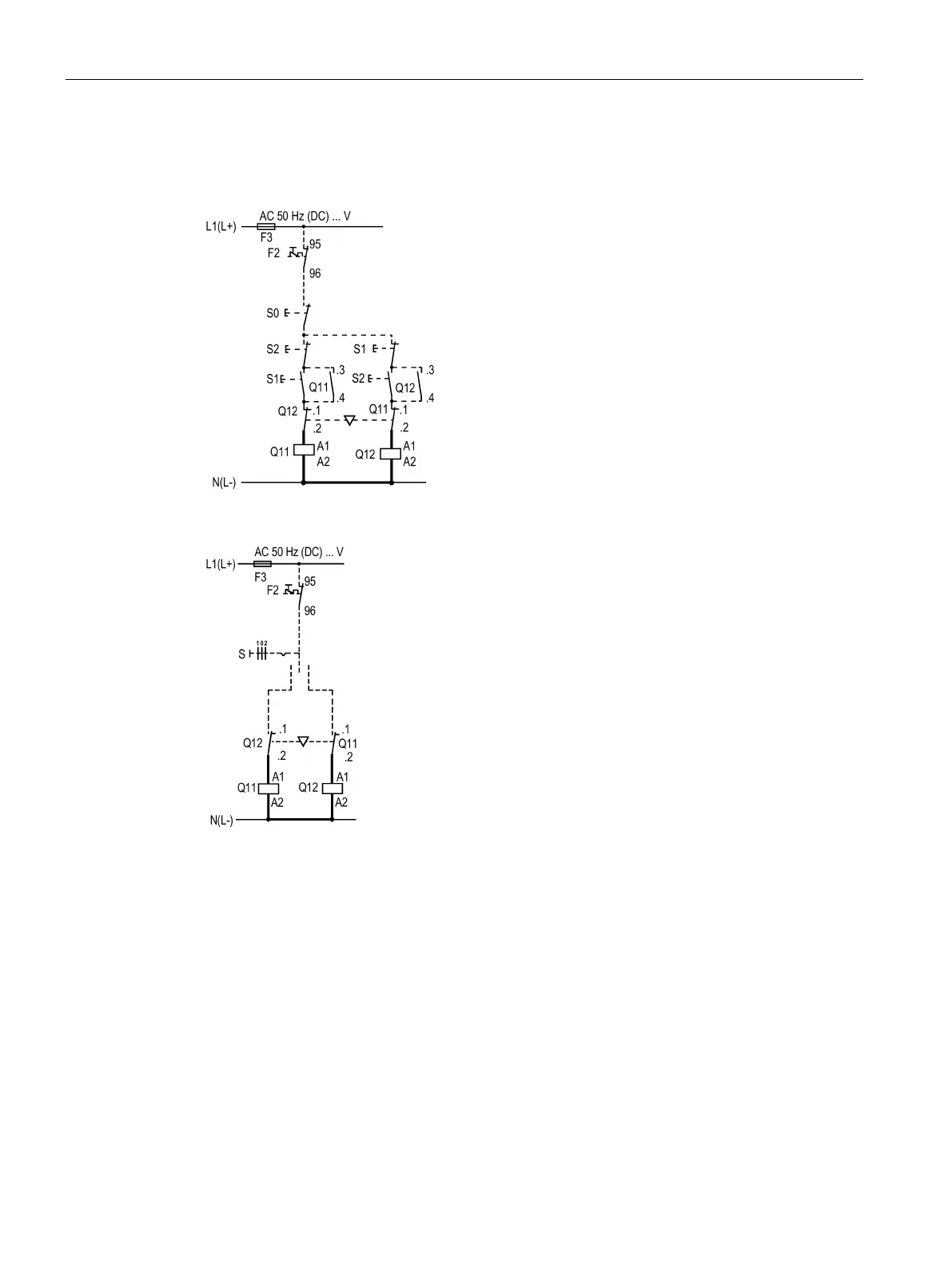
Circuit diagr
ams
11.5
Rev
ersing c
ontac
tor as
semblies (
S6 / S
10 / S12)
SIRIU
S
-
SIRIUS 3RT Contactors/Contact
or assemblies
486
Manual
,
09/2017
,
A5E03656507120A/
RS
-
AE/006
Cont
ro
l circ
uit
Pushbutto
n switch
contro
l
Maintaine
d
-
contac
t operati
on
485
487
Table of Contents
Main Page
Default Chapter
5
Table of Contents
5
1 Introduction
13
Responsibility of the User for System Configuration and Functionality
13
Purpose of the Manual
14
Advantages through Energy Efficiency
15
Required Basic Knowledge
15
Scope of the Manual
15
Siemens Industry Online Support
16
Further Documentation
17
Datamatrix Code
18
Siemens Industry Online Support App
18
Recycling and Disposal
19
Technical Assistance
19
2 Standards
21
Standards and Product Approvals
21
Protective Separation
23
Positively Driven Contact Elements/Mirror Contacts
24
Used for Stop Category 0 / 1
25
IE3 / IE4 Ready
26
Applications
27
3 Safety Instructions
29
General Safety Notes
29
Intended Use
30
Current Information about Operational Safety
30
4 Product Description
31
Overview of the Contactor Range
31
Device Versions
35
3RT2 Power Contactors
36
3RT10 / 3RT14 Power Contactors and 3RT12 Vacuum Contactors
41
3RH2 Contactor Relays
47
3RT26 Capacitor Contactors
50
3RA23 Reversing Contactor Assemblies
56
3RA24 Contactor Assemblies for Star-Delta (Wye-Delta) Start
59
Drive Options
63
Reference
63
5 Product Combinations
65
6 Configuration
67
Overview of Applications for Contactors and Contactor Assemblies
67
SIRIUS System Configurator
68
Operating Mechanism System / Coil Selection 3RT Contactors and 3RH2 Contactor Relays
69
Relays
69
Operating Mechanism System / Coil Selection 3RT1 Contactors
70
Conventional Operating Mechanism
72
Solid-State Operating Mechanism for Standard Contactors
73
Solid-State Operating Mechanism for Standard Contactors with Remaining Lifetime Signal RLT
77
Solid-State Operating Mechanism for Contactors with Extended Operating Range and Rail Applications
83
Solid-State Operating Mechanism for Contactors with Fail-Safe Control Input
85
Typical Circuit Diagrams (Standard Contactors)
87
Application Environment
89
3RH2 Contactor Relays
89
3RT Power Contactors
90
Contactors for Railway Applications
93
Installation Altitude
94
Switching Motorized Loads
95
Switching Resistive Loads
100
Changing the Polarity of Hoisting Gear Motors
103
Switching in the Auxiliary Circuit
105
Switching of Capacitive Loads
106
Contactors with Extended Operating Range
114
Contactors for Rail Applications According to IEC 60077-2
114
Coupling Relays
116
Technical Background Information
117
Contactors in Safety Applications
118
Safety Notes
118
General Safety Notes
118
Intended Use
119
Current Information about Operational Safety
121
Security Information
121
Examples/Applications
122
User Responsibility for System Design and Function
122
Safety Information
123
Layout of Application Examples
124
P-Switching Fail-Safe Outputs
125
PM-Switching Fail-Safe Outputs
132
Operation of a Motor in Two Directions of Rotation (Reversing Contactor Assembly)
140
Reference
146
Starting Three-Phase Motors with Reduced Starting Current Peaks (Contactor Assembly for Star-Delta (Wye-Delta) Start)
147
Reference
152
Technical Background Information
153
Using Long Control Cables
158
Configuration Information for Use Downstream of Frequency Converters
164
Contact Service Life of Auxiliary and Main Contacts
166
3RT2 Power Contactors (Sizes S00 to S3)
166
Contact Service Life of Auxiliary and Main Contacts (Sizes S00 and S0)
166
Contact Service Life of Auxiliary and Main Contacts (Size S2)
169
Contact Service Life of Auxiliary and Main Contacts (Size S3)
171
3RT26 Capacitor Contactors (Sizes S00 to S3)
173
6.16 Contact Service Life of Auxiliary and Main Contacts
173
3RT10 Power Contactors and 3RT12 Vacuum Contactors (Sizes S6 to S12)
175
Mechanical Endurance
175
Electrical Endurance
175
7 Mounting
179
Warning Notice
179
Mounting Options
179
Mounting Position
180
Mounting on Mounting Plate / Wall Mounting
181
Snapping Onto DIN Rail (Snap-On Mounting)
185
Replacing Solenoid Coils
188
Replacing Solenoid Coils for Size S0
188
Replacing Solenoid Coils for Size S2
191
Replacing Solenoid Coils for Size S3
196
Replacing Solenoid Coils for Sizes S6-S12
202
Contact Piece Replacement (Sizes S2 to S12)
205
Contact Piece Replacement (Size S2)
205
Contact Piece Replacement (Size S3)
211
Contact Piece Replacement (Size S6)
217
Contact Piece Replacement (Size S10 and S12)
219
Replacing the Vacuum Interrupters (Sizes S10 and S12)
222
8 Connection
227
Warning Notice
227
Conductor Cross-Sections
230
Conductor Cross-Sections for Screw-Type Connection Systems
230
Conductor Cross-Sections for Spring-Loaded Connection Systems
238
Conductor Cross-Sections for Ring Cable Lug Connection System
240
9 Accessories
243
Overview of Accessories for 3RT2 Contactors
243
Overview of Accessories for 3RT1 Contactors
253
Auxiliary Switch Blocks
255
Auxiliary Switch Block for 3RT2 Power Contactors and 3RH2 Contactor Relays
255
Description
255
Configuration
258
Selection Guide for Mountable Auxiliary Switch Blocks for Power Contactors and Contactor Relays
264
Mounting/Disassembly
284
Auxiliary Switch Blocks for 3RT1 Power Contactors
287
Description
287
Configuration
290
Terminal Designations and Identification Numbers for Auxiliary Contacts
292
Mounting/Disassembly
293
Surge Suppressor
296
Description
296
Configuration
300
Mounting
308
EMC Suppression Module
315
Description
315
Configuration
317
Mounting
319
OFF-Delay Device
320
Description
320
Configuration
320
Mounting
321
Mechanical Latch
323
Description
323
Mounting/Disassembly
324
Operation
326
Additional Load Module
327
Description
327
Mounting
327
Control Kit for Manual Operation of Contactor Contacts
328
Description
328
Mounting
329
Coupling Link for PLC
331
Description
331
Mounting the 3RH2924-1GP11 Coupling Link
334
Mounting and Disassembling the 3RH2926-1AP1 Coupling Module
335
LED Display Indicator Module
338
Description
338
Mounting
339
Solder Pin Adapter
340
Description
340
Mounting
341
Coil Terminal Module
343
SIRIUS - SIRIUS 3RT Contactors/Contactor Assemblies Manual, 09/2017, A5E03656507120A/RS
343
Description
343
Mounting
344
Cover for Ring Cable Lug
346
Description
346
Sealable Cover
347
Description
347
Mounting
347
3-Phase Infeed Terminal
348
Description
348
Mounting
348
1-Phase Infeed Terminal
349
Description
349
Mounting
349
Parallel Switching Connectors
350
Description
350
Configuration
351
Mounting
353
Link Module for Two Contactors in Series
354
Description
354
Mounting
354
Link Module for Motor Starter Protector
356
Description
356
Pneumatically Delayed Auxiliary Switch
357
Description
357
Mounting/Disassembly
358
Operation
359
Insulating Stop
360
Description
360
Terminal Module for Contactors with Screw Connections
361
Description
361
Mounting
362
3RA27 Function Modules for Connection to the Automation Level (AS-Interface or IO- Link)
363
Description
363
3RA28 Function Modules for Mounting on 3RT2 Contactors
364
Description
364
Assembly Kit for Reversing Contactor Assemblies (Sizes S00 to S3)
366
Description
366
Mounting Size S00
368
Mounting Size S0
371
Mounting Size S2
376
Mounting Size S3
380
Wiring Kit for Reversing Contactor Assemblies (Sizes S6 to S12)
385
Description
385
Mounting Size S6
386
Mounting Sizes S10 and S12
389
Assembly Kit for Contactor Assemblies for Star-Delta (Wye-Delta) Start (Sizes S00 to S3)
391
Description
391
Mounting Size S00
395
Mounting Size S0
399
Mounting Size S2
404
Mounting Size S3
415
Wiring Kit for Contactor Assemblies for Star-Delta (Wye-Delta) Start (Sizes S6 to S12)
427
Description
427
Mounting Size S6
429
Mounting Sizes S10 and S12
435
Terminal Cover for Cable Lug Connection and Busbar Connection
439
Description
439
Mounting
441
Terminal Covers for Box Terminal Block
450
Description
450
Mounting
450
Main Current Path Surge Attenuation Module for Vacuum Contactors
451
Description
451
Mounting
452
Box Terminal Block (Size S6 to S12)
454
Description
454
Mounting
455
Solid-State Time-Delay Auxiliary Switch Blocks (Size S6 to S12)
456
Description
456
Configuration
459
Mounting/Disassembly
459
10 Technical Data
461
Technical Data in Siemens Industry Online Support
461
Overview Tables
461
11 Circuit Diagrams
463
Cax Data
463
Contactors and Contactor Accessories
464
Capacitor Contactors (S00 /S0 / S2 / S3)
480
Reversing Contactor Assemblies (S00 / S0 / S2 / S3)
484
Reversing Contactor Assemblies (S6 / S10 / S12)
485
Contactor Assemblies for Star-Delta (Wye-Delta) Start (S00 / S0 / S2 / S3)
487
Contactor Assemblies for Star-Delta (Wye-Delta) Start (S6 / S10 / S12)
490
Types of Coordination
493
References
495
B.1 References
495
Manuals - SIRIUS Modular System
497
B.3 more Information
499
More Information
499
Dimension Drawings (Dimensions in MM)
501
Cax Data
501
C.1 Cax Data
501
3RT2.1 Contactors and 3RH2 Contactor Relays (Size S00)
502
3RT2.2 Contactors (Size S0)
508
3RT2.3 Contactors (Size S2)
514
3RT2.4 Contactors (Size S3)
518
3RT1.5 Contactors (Size S6)
522
3RT1.6 Contactors (Size S10)
523
3RT1.7 Contactors (Size S12)
524
3RT26 Capacitor Contactors
525
3RT261 Capacitor Contactors (Size S00)
525
3RT262 Capacitor Contactors (Size S0)
526
3RT263 Capacitor Contactors (Size S2)
529
3RT264 Capacitor Contactors (Size S3)
530
3RA23 Reversing Contactor Assemblies
531
3RA231 Reversing Contactor Assemblies (Size S00)
531
3RA232 Reversing Contactor Assemblies (Size S0)
533
3RA233 Reversing Contactor Assemblies (Size S2)
537
3RA234 Reversing Contactor Assemblies (Size S3)
538
3RA234.-8X.30-1 Reversing Contactor Assemblies (Size S3)
538
Drilling Diagram for 3RA234.-8X.30-1 Reversing Contactor Assemblies (Size S3)
538
3RA24 Contactor Assemblies for Star-Delta (Wye-Delta) Start
539
3RA241 Contactor Assemblies for Star-Delta (Wye-Delta) Start (Size S00)
539
3RA242 Contactor Assemblies for Star-Delta (Wye-Delta) Start (Size S0)
541
3RA242.-8X.3.-1 Contactor Assemblies for Star-Delta (Wye-Delta) Start (Size S0, Screw- Type Connection System)
541
Drilling Diagram for 3RA242.-8X.3.-1 Contactor Assemblies for Star-Delta (Wye-Delta) Start (Size S0, Screw-Type Connection System)
541
3RA242.-8X.3.-2 Contactor Assemblies for Star-Delta (Wye-Delta) Start (Size S0, Spring-Loaded Connection System)
542
Drilling Diagram for 3RA242.-8X.3.-2 Contactor Assemblies for Star-Delta (Wye-Delta) Start (Size S0, Spring-Loaded Connection System)
542
3RA243 Contactor Assemblies for Star-Delta (Wye-Delta) Start (Size S2)
543
3RA244 Contactor Assemblies for Star-Delta (Wye-Delta) Start (Size S3)
545
3RA244.-8X.32-1 Contactor Assemblies for Star-Delta (Wye-Delta) Start (Size S3)
545
Drilling Diagram for 3RA244.-8X.32-1 Contactor Assemblies for Star-Delta (Wye-Delta) Start (Size S3)
546
Index
547
Related product manuals
Siemens SIRIUS 3RU
206 pages
Siemens SIRIUS 3RW5
116 pages
Siemens SIRIUS 3RT2
84 pages
Siemens SIRIUS 3RA2712 C Series
8 pages
Siemens SIRIUS 3SB3 Series
16 pages
Siemens SIRIUS ACT 3SU1
610 pages
SIRIUS ACT 3SU1400 EK10-6AA0 Series
8 pages
Siemens SIMATIC
648 pages
Siemens SINUMERIK
300 pages
Siemens SIMOCODE pro
286 pages
Siemens SINAMICS V60
40 pages
Siemens SIMATIC TI500
94 pages