Configuration
6.3 Operating mechanism system / coil selection 3RT contactors and 3RH2 contactor relays
SIRIUS - SIRIUS 3RT Contactors/Contactor assemblies
80 Manual, 09/2017, A5E03656507120A/RS-AE/006
"Remaining lifetime RLT" signal
Upon reaching a remaining lifetime of 20 %, the "remaining lifetime RLT" signal is available
at terminals R1/R2 via a floating relay contact (NO contact, hard gold-plated, enclosed) and
can be input to SIMOCODE, PLC or other devices for processing, for example. Permissible
current-carrying capacity of the R1/R2 relay output:
I
e
/AC-15 at 24 ... 230 V: 3 A
I
e
/DC-13 at 24 V: 1 A
The contactors can be controlled as follows:
● via a 24 V DC control signal
● via relay outputs, e.g. of PLC, SIMOCODE.
To supply the solenoid operating mechanism and the remaining lifetime signal with power,
the control supply voltage U
s
must be connected to terminals A1/A2 of the laterally mounted
electronic module.
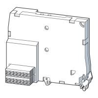
The control inputs of the contactor are connected to a 7-pole plug-in connection (the spring-
loaded connector is part of the scope of supply).
Changeover from automatic to local control
Automatic control can be changed over to local control via inputs H1/H2. During
commissioning or in the event of a fault, for example, automatic control via PLC or
SIMOCODE can be deactivated and the contactor can be controlled manually.

 Loading...
