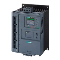
PROFIBUS DP Communication Module
SIRIUS 3RW44 manual
8-2 GWA 4NEB 535 2195-02 DS 06
8.6.3 Integration into the User Program 8-21
8.6.4 Switching On 8-21
8.6.5 Flow Diagram PROFIBUS DP - Starting the Soft Starter 8-22
8.7 Process Data and Process Images 8-23
8.8 Diagnosis via LED Display 8-25
8.9 Diagnosis with STEP 7 8-26
8.9.1 Reading the Diagnosis 8-26
8.9.2 Options for Reading the Diagnosis 8-26
8.9.3 Structure of the Slave Diagnosis 8-27
8.9.4 Station Status 1 to 3 8-28
8.9.5 Master PROFIBUS Address 8-30
8.9.6 Manufacturer Code 8-30
8.9.7 Code-Based Diagnosis 8-31
8.9.8 Module Status 8-32
8.9.9 Channel-Based Diagnosis 8-33
8.10 Data Formats and Data Sets 8-35
8.10.1 Characteristics 8-35
8.11 Identification Number (ID No.), Error Codes 8-38
8.11.1 Identification Number (ID No.) 8-38
8.11.2 Error Codes for Negative Data Set Acknowledgement 8-38
8.12 Data Sets 8-40
8.12.1 Data Set 68 - Reading/Writing the Process Image of the Outputs 8-41
8.12.2 Data Set 69 - Reading the Process Image of the Inputs 8-42
8.12.3 Data Set 72 - Log List - Reading Device Errors 8-43
8.12.4 Data Set 73 Log List - Reading the Trippings 8-44
8.12.5 Data Set 75 Log List - Reading Events 8-44
8.12.6 Data Set 81 - Reading the Basic Settings of Data Set 131 8-48
8.12.7 Data Set 82 - Reading the Basic Settings of Data Set 132 8-48
8.12.8 Data Set 83 - Reading the Basic Settings of Data Set 133 8-48
8.12.9 Data Set 92 - Reading the Device Diagnosis 8-49
8.12.10 Data Set 93 - Writing a Command 8-55
8.12.11 Data set 94 - Reading the Measured Values 8-56
8.12.12 Data Set 95 - Reading the Statistics Data 8-57
Chapter Subject Page

 Loading...

