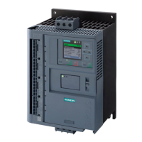
PROFIBUS DP Communication Module
SIRIUS 3RW44 manual
GWA 4NEB 535 2195-02 DS 06
8-21
8.6.3 Integration into the User Program
Table 8-5: Integration into the User Program
8.6.4 Switching On
Table 8-6: Switching on
Step Description
1
Create the user program in the LAD/STL/CSF editor in OB1.
Example: Reading an input and controlling an output:
2
Save the project in the SIMATIC manager.
3
Load the configuration into the DP master.
Cyclically copy the central DIs (switches) to the decentralized motor starter (=PAA).
Cyclically output the PAE of the motor starter to the central DOs (LED).
// PAA: read in switches 0-7 (DI 16 x 24 V DC)
// y emitir al arrancador de motor
// EB0.0 Motor - RIGHT
// EB0.1 Motor - LEFT
// EB0.2 0
// Read in the motor starter PAE
// and output to D016xDC24V
Step Description
1
Switch on the voltage supply for the soft starter.
2
Observe the status LEDs on the DP master CPU315-2 DP:
5 V DC: Lights up
SF DP: Off
BUSF: Off
3
Observe the status LEDs on the PROFIBUS module:
LED BUS: Lights up green

 Loading...

