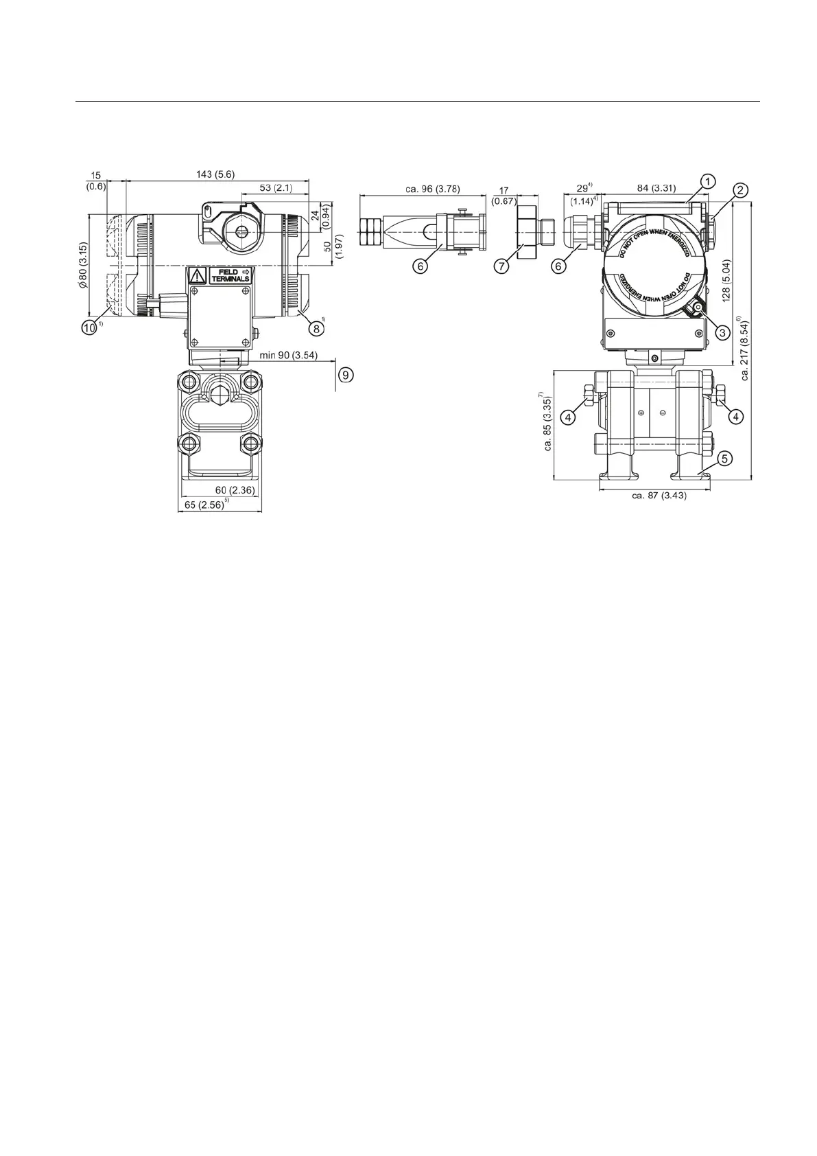
Dimension drawings
14.2 SITRANS P DS III for differential pressure, flow rate and absolute pressure from the differential pressure
series
SITRANS P DS III with PROFIBUS PA
Operating Instructions, 06/2013, A5E00053276-07
225
Cover catch (only for "flameproof enclosure" type of protection)
Sealing plug, with valve (optional)
1
Electrical connection:
• Pg 13.5 gland (adapter)
2)3)
• M20 x 1.5 gland
3)
•
1
/
2
-14 NPT gland
• Han 7D/Han 8D plug
2) 3)
• M12 connector
Space for enclosure rotation
8)
Electronics side, display (longer for cover with inspection window)
1)
Take an additional 20 mm (0.79 inches) thread length into account
2)
Not with "flameproof enclosure" type of protection
3)
Not for "FM + CSA [is + XP]" type of protection
4)
For Pg 13.5 with adapter, approx 45 mm (1.77 inches)
5)
74 mm (2.9 inch) for PN ≥ 420 (MAWP ≥ 6092 psi)
6)
219 mm (8.62 inches) for PN ≥ 420 (MAWP ≥ 6092 psi)
7)
91 mm (3.6 inches) for PN ≥ 420 (MAWP ≥ 6092 psi)
8)
92 mm (3.62 inches) minimum distance for rotating the enclosure with display
Figure 14-3 Pressure transmitter SITRANS P DS III for differential pressure and flow rate with caps for vertical differential
pressure lines, dimensions in mm (inches)
 Loading...