Description
3.4 Nameplate layout
SITRANS P DS III with PROFIBUS PA
Operating Instructions, 06/2013, A5E00053276-07
25
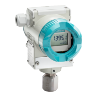
● Depending on the device version, the front cover ② may be designed as an inspection
window. You can read the measured values straight off the digital display through this
inspection window.
● The cable inlet
⑧ to the electrical terminal compartment is at the side; either the left or
right-hand one can be used. The unused opening is closed with a blanking plug
⑬.
● The protective conductor terminal/equipotential bonding terminal
⑪ is located at the back
of the enclosure.
● The electrical terminal compartment
⑩ for the auxiliary power and shield is accessible
when you remove the back cover
⑨.
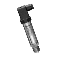
● The measuring cell with a process connection
⑥ is located in the lower section of the
enclosure. This measuring cell is secured against twisting by a retaining screw
⑤.
Thanks to the modular structure of the transmitter, the measuring cell, the electronic unit
or the network card can be replaced if required.
● On the upper face of the enclosure you can see crosshead screws which secure the key
cover
①, under which there are 3 keys for local operation.
Nameplate layout
Nameplate with general information
The label which bears the Order No. and other important information such as design details
or technical data is present on the side of the housing.
Order number (machine-readable product
Serial number
Figure 3-3 Example of a nameplate
 Loading...