4100ES-S1 Programming Guide Document: LT0400
Addressable Device Settings
6-8
[END INPUTS]
[OUTPUTS]
TRACK ON PRI=9,9
M1-7-1 | MRELAY | RELAY | TEST SOLENOID
[END OUTPUTS]
9) Create another Custom Control equation, this time for the Print statement on the panel
display as follows:
[INPUTS]
STATUS ON
M1-7-1 | MRELAY | RELAY | TEST SOLENOID
[END INPUTS]
[OUTPUTS]
PRINT ALL "RELEASE BUTTON TO STOP SOLENOID TEST"
[END OUTPUTS]
10) Alter CC equation 6-32 by changing the output statement from Hold to Track. This will allow
the Solenoid to turn off when the button is released.
[INPUTS]
STATUS ON
P514 | DIGITAL | UTILITY | ALARM TEST
AND STATUS ON
P916 | DIGITAL | UTILITY | MULTIFUNCTION SWITCH - ZONE 16
[END INPUTS]
[OUTPUTS]
TRACK ON PRI=9,9
P1016 | DIGITAL | FIRE | ALARM TEST ZONE 16
[END OUTPUTS]
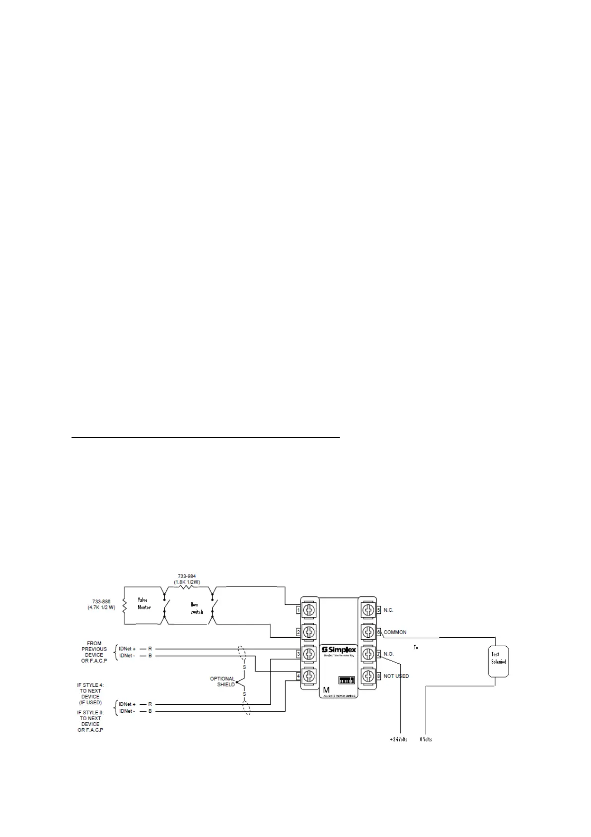
TRIAM – Flow Switch / Test Solenoid/ Valve Monitor
Repeat above but use WSO in place of WATER for the point type and wire a 1K8Ω resistor
in series with the normally open contacts of the monitor valve. The flow switch will give a
S/C. The Valve Monitor will be a current limited S/C and be shown as an Isolate for AZF 16.
1) Program a TRIAM – Utility (M1-7-0 in our example).
2) M1-7-1 – MRELAY – Point Type RELAY – Test Solenoid.
3) M1-7-2 – MTSENSE – Point Type WSO – Flow Switch/ Monitor AZF 16.