4100ES-S1 Programming Guide Document: LT0400
Appendices
12-20
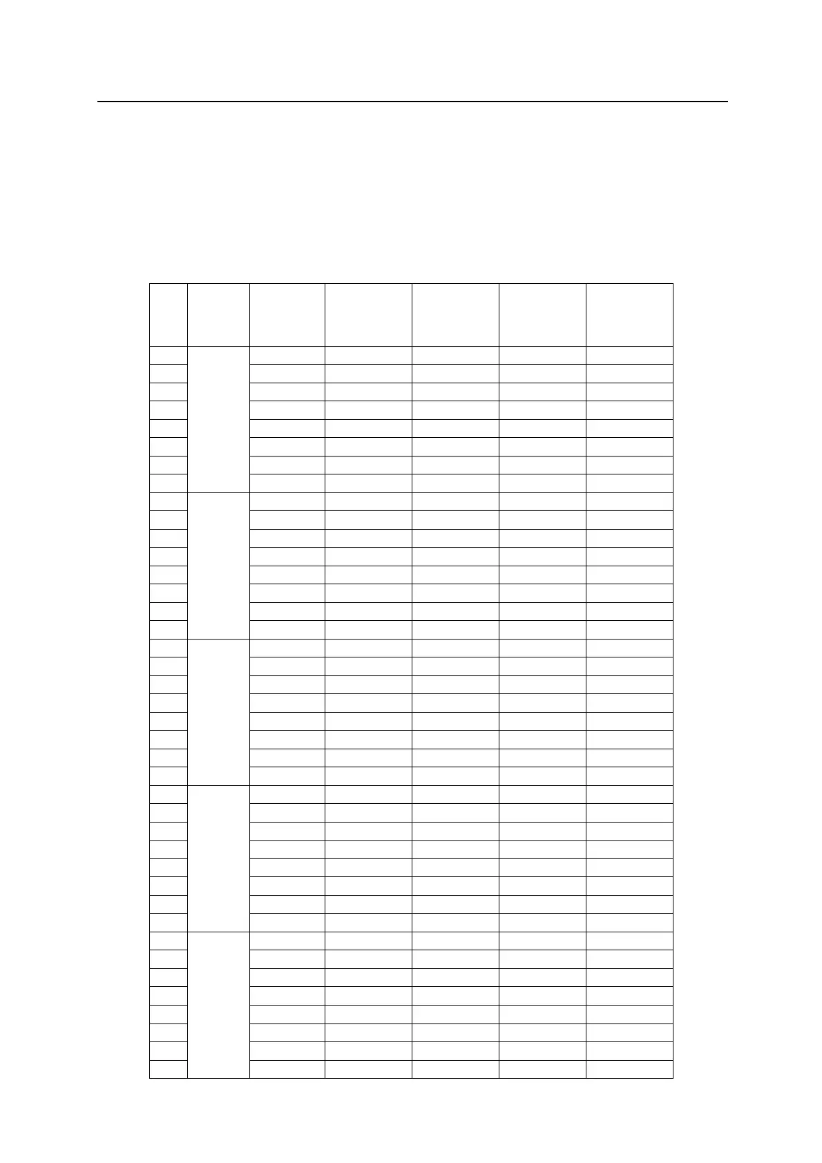
12.5 Appendix E - 4100-1282 AZF Switch and LED Address
Mapping
The following table displays the fixed mapping of zones to Display modules (using
4100-1282) with HW Ref Addresses of the Push-Buttons, the Alarm LEDs and the Isolate
LEDs, and their matching Pseudo Points.
This uses the standard card addressing in 4100ES-S1 which has the first LED controller at
address 3 (up to 32 zones) and the second LED controller at address 4 (33-64 zones).
HW Ref.
Push-
Button
Address
Push-Button
Pseudo
point Ref.
Address
HW Ref.
Alarm LED
Address
HW Ref.
Isolate LED
Address
LED Pseudo
point Ref.
Address