4100ES-S1 Programming Guide Document: LT0400
Appendices
12-16
12.4 Appendix D - Custom Control for Alarm Zone Facilities
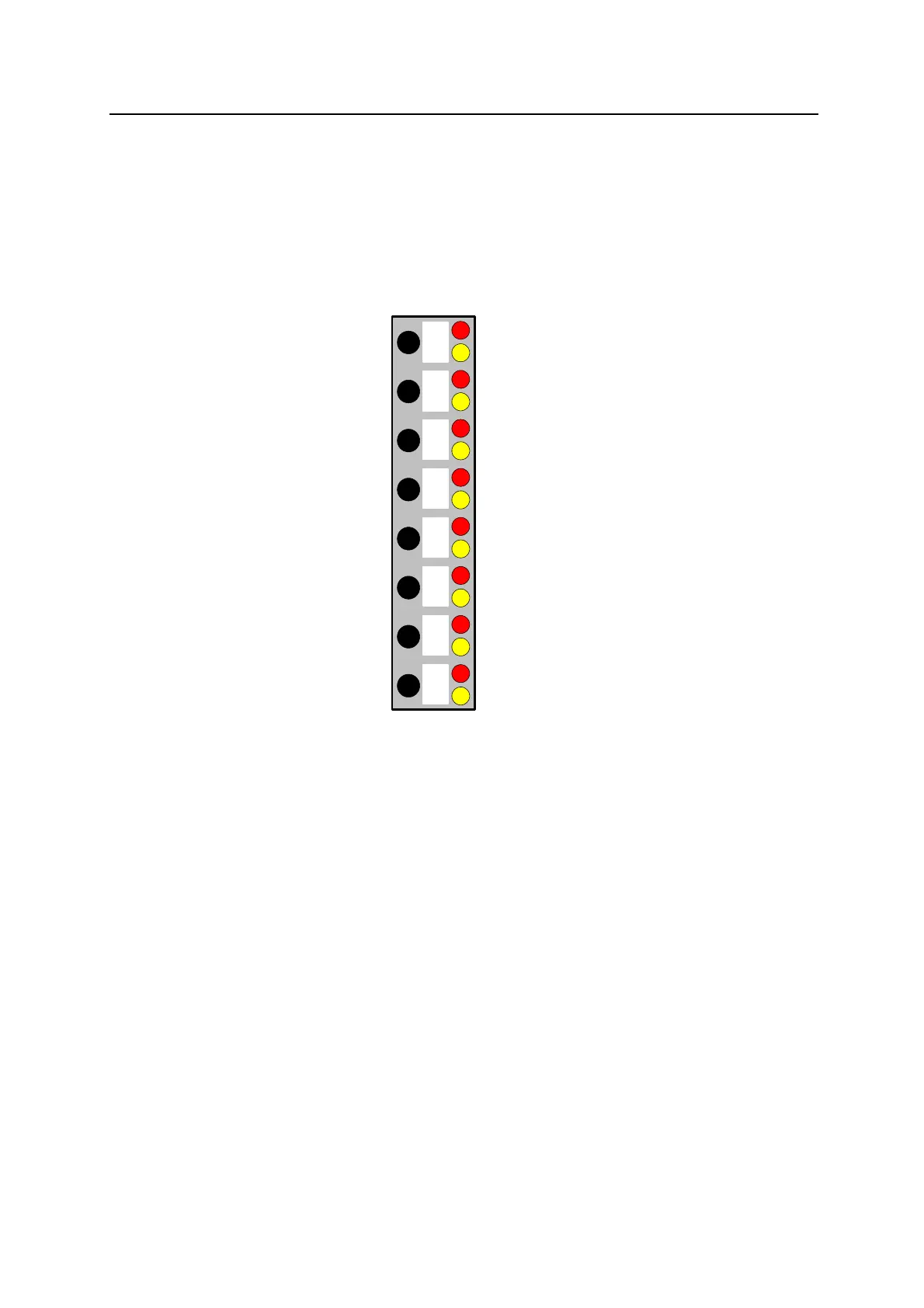
A 4100-1282 8 Pushbutton/8 red LED/8 amber LED module is fitted for each 8 zones to
display the alarm and isolate states of the zones (lists) and allow the zone to be isolated,
alarm tested or fault tested.
This diagram shows the point numbers used for the push buttons and LEDs, where n = zone
number. A number of pseudo digital points are used for each zone to store and control the
operation.
3-65 Zone 1 Multifunction Button (P901)
x-x Zone n Multifunction Button (P900+n)
3-1 Zone 1 Alarm LED
3-2 Zone 1 Isolate LED (P601)
x-x Zone n Alarm LED
x-x Zone n Isolate LED (P600+n)
12.4.1 Digital Points used
Zone 1
P601 – Zone 1 is Isolated
P701 – Zone 1 Isolate Toggle
P801 – Zone 1 is in Alarm
P901 – Zone 1 Multifunction pushbutton
P1001 – Zone 1 is in Alarm Test
P1101 – Zone 1 is in Fault Test
Zone n
P600+n – Zone n is Isolated
P700+n – Zone n Isolate Toggle
P800+n – Zone n is in Alarm
P900+n – Zone n Multifunction pushbutton
P1000+n – Zone n is in Alarm Test
P1100+n – Zone n is in Fault Test