Simrad AP35 Autopilot
46 22083083H
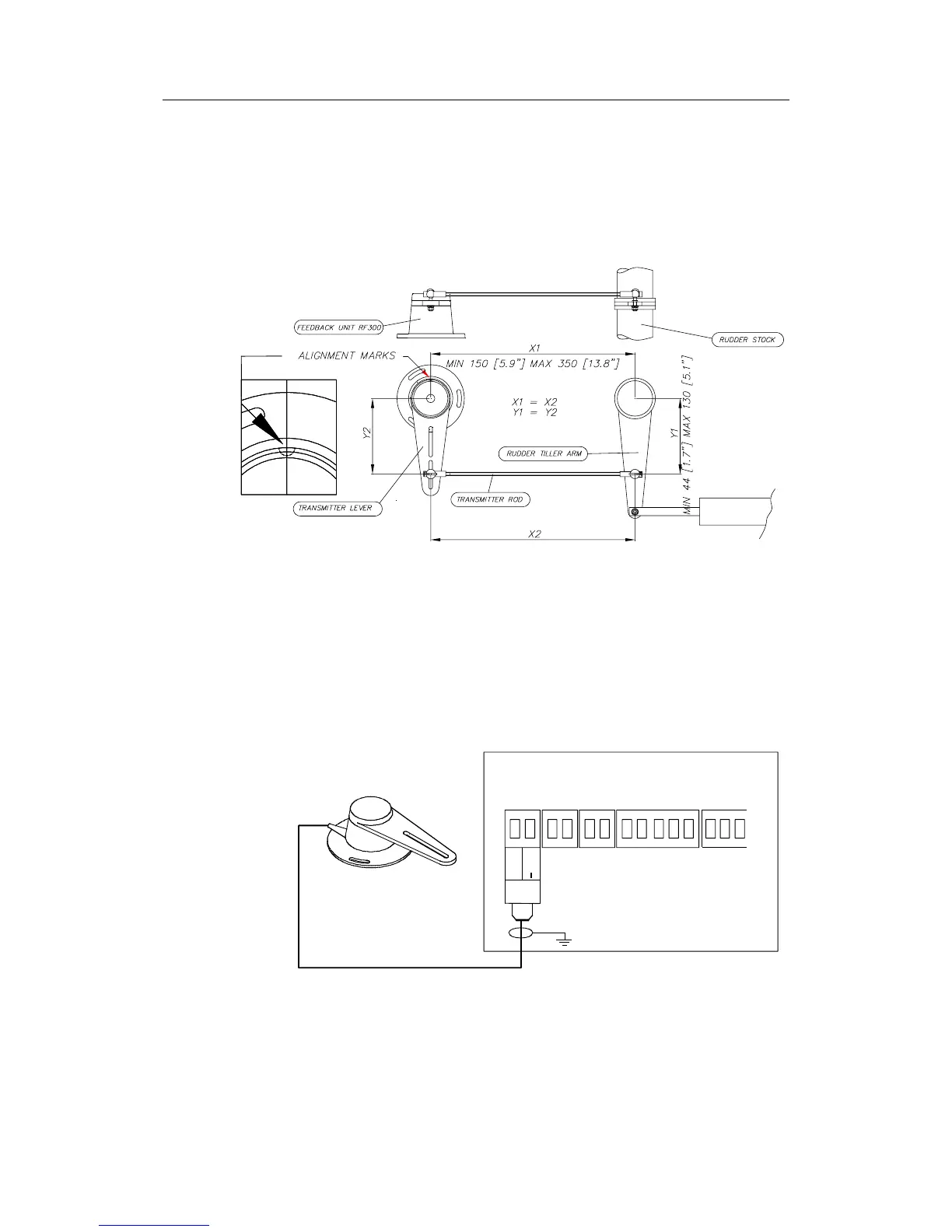
Attach the transmitter rod to the RF300. Set the RF300 mounting location to
be in accordance with Figure 4-2. The centre of the RF300 should be in line
with the centre of the rudder post. Mount the RF300 to a suitable platform
using the screws provided. If necessary, add blocking material under the
RF300 to adjust the height of the transmission arm to be level with the
rudder tiller arm.
Figure 4-2 RF300 mounting (019356)
Note ! Due to space limitations, it may be necessary to cut the length of the
transmitter rod to move the RF300 closer to the rudder post.
Tighten the mounting screws for both the RF300 feedback unit and the
transmitter rod ball joint.
Have someone observe the RF300 while someone else turns the helm wheel
through the complete range of travel from full port to full stbd. rudder to
verify that the mechanical linkage to the RF300 is not obstructed.
JUNCTION UNIT
MAIN PCB
Rudder
Feedb.
*
* NON POLARIZED
(COLOR INDEPENDENT)
RF +
RF
Figure 4-3 RF300 connection