Installation
22083083H 55
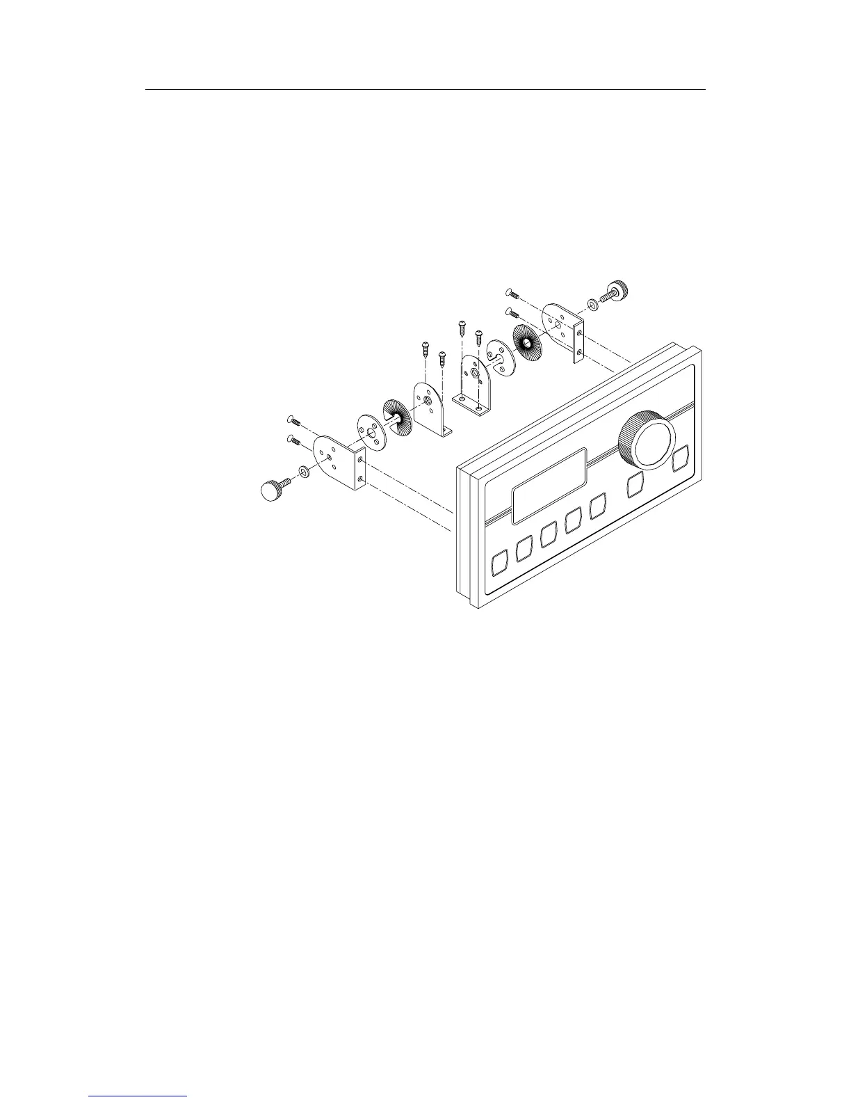
• Remove the Control unit, drill the 4 mounting holes in the mounting
surface.
• Unbolt the temporarily fitted bracket halves and screw them to the
mounting surface.
• Assemble the complete bracket again and adjust the control head to best
viewing angle and tighten up the mounting bracket bolts.
• Connect the Robnet cables to the control unit connectors (See note on
next page).
Figure 4-12 AP35 Bracket mounting
ROBNET network cables
As Robnet units have 2 Robnet connectors they can be used as "jack points"
for further expansion of the system. There are no dedicated "in" or "out"
connectors. You may connect the cables to any available Robnet connector
on the specific unit.
The Robnet cables are available in 7 and 15 m length and provided with 6
pin male connector at one or both ends. The 15 m cable to the junction unit
has connector only at the control unit end.
Optional extension cable (10 m) is available and have a male and a female
connector.
When installing a system, try to minimize total Robnet cable length by
connecting all Robnet units to the nearest available Robnet connector.
Total length of Robnet cable installed in a system should not exceed 50 m
(165').
Examples of interconnecting Robnet units: