Installation
22083083H 47
4.7 RF45X Rudder Feedback Unit
The RF45X is normally installed with the shaft pointing upwards. It can,
however, be mounted with the shaft pointing downwards if this is more
convenient. The deflection can then be inverted as illustrated in Figure 4-5. An
“upside-down” installation will make access to within the unit more
convenient as the unit can be opened without moving it from the mounting
base. To open the unit, unscrew the two screws at the bottom and remove the
cover. Be careful with the wires when you put back the cover.
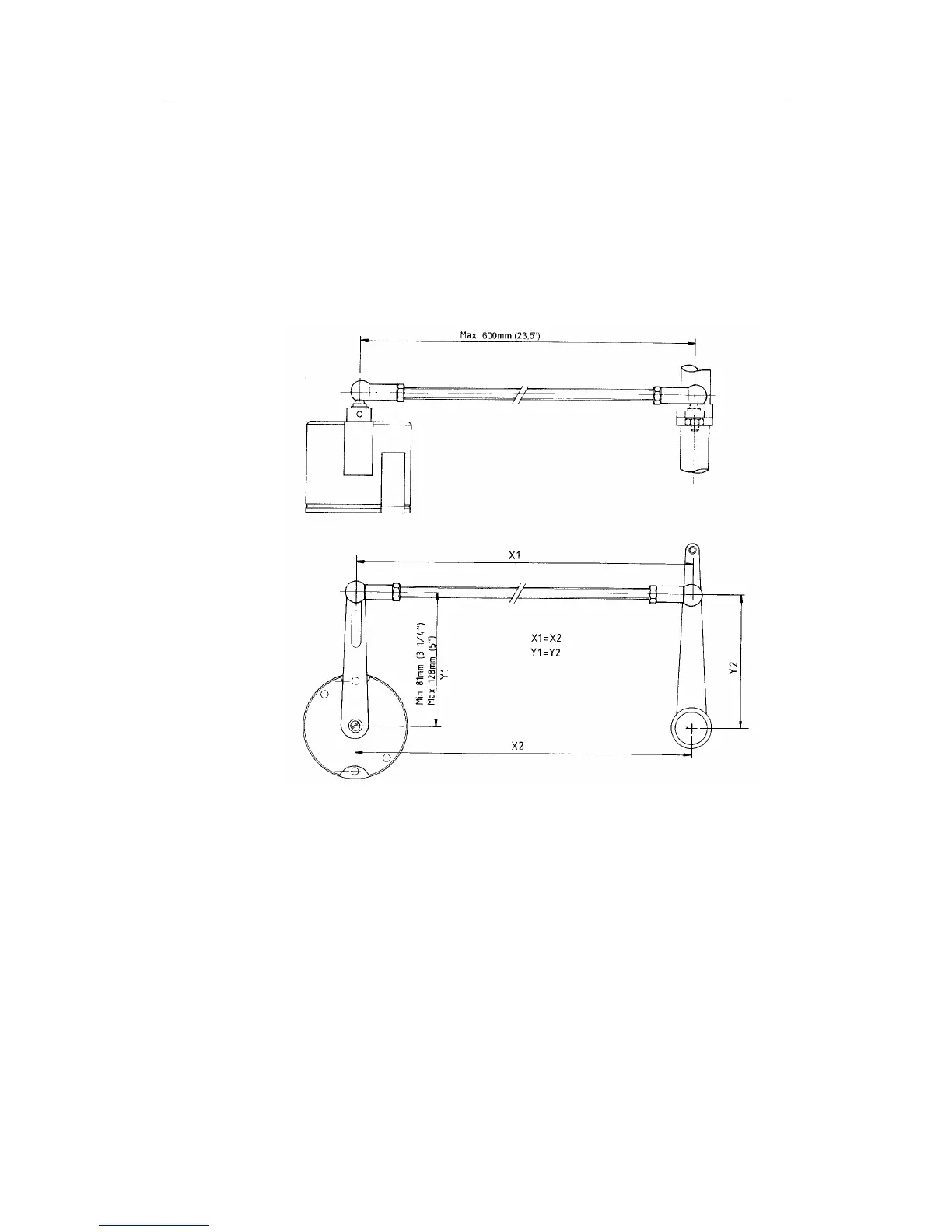
Figure 4-4 RF45X Rudder Feedback Unit - Mounting
Use the attached template (Drw. 22011225) to drill the required mounting
holes. The unit is fastened to the mounting base by the two Allen screws
enclosed. (Other types of screws may be used if fastened to i.e. a wooden
base.)
Make the parallelogram configuration of the transmission link (see Figure 4-4)
and temporarily fasten the link to the RF45X shaft. The transmission rod can
be shortened by cutting off a piece using a hacksaw. Move the rudder
manually h.o. - h.o. and make sure the transmission link is moving freely in
both directions.