Simrad AP35 Autopilot
48 22083083H
Electrical connection
Use a twisted pair cable AWG20 (0.5 mm
2
) between the breakout box and the
J3xx junction unit. The cable length is not critical but should be kept at a
minimum.
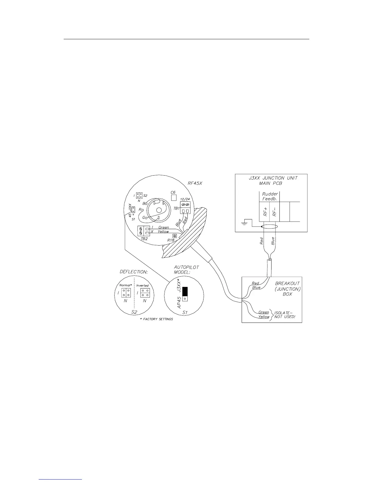
The cable should be connected to the junction unit according to Figure 4-5.
When splicing the cables in the breakout box, crimp the enclosed pins on
each wire of the extension cable. Otherwise the wires may be cut off at the
terminal point when the screws are tightened.
The screen is not terminated in RF45X and must be connected in the
junction unit.
Note ! The green and yellow wire is not used and must be isolated!
For final alignment, see page 75.
Figure 4-5 RF45X Connection