Simrad AP35 Autopilot
56 22083083H
CONTROL
UNIT
JUNCTION
UNIT
NI300X
CONTROL
UNIT
CONTROL
UNIT
JUNCTION
UNIT
NI300X
CONTROL
UNIT
All connectors are crimp type, which can be easily dismantled if required in
an installation where you can not drill holes as big as the connector is.
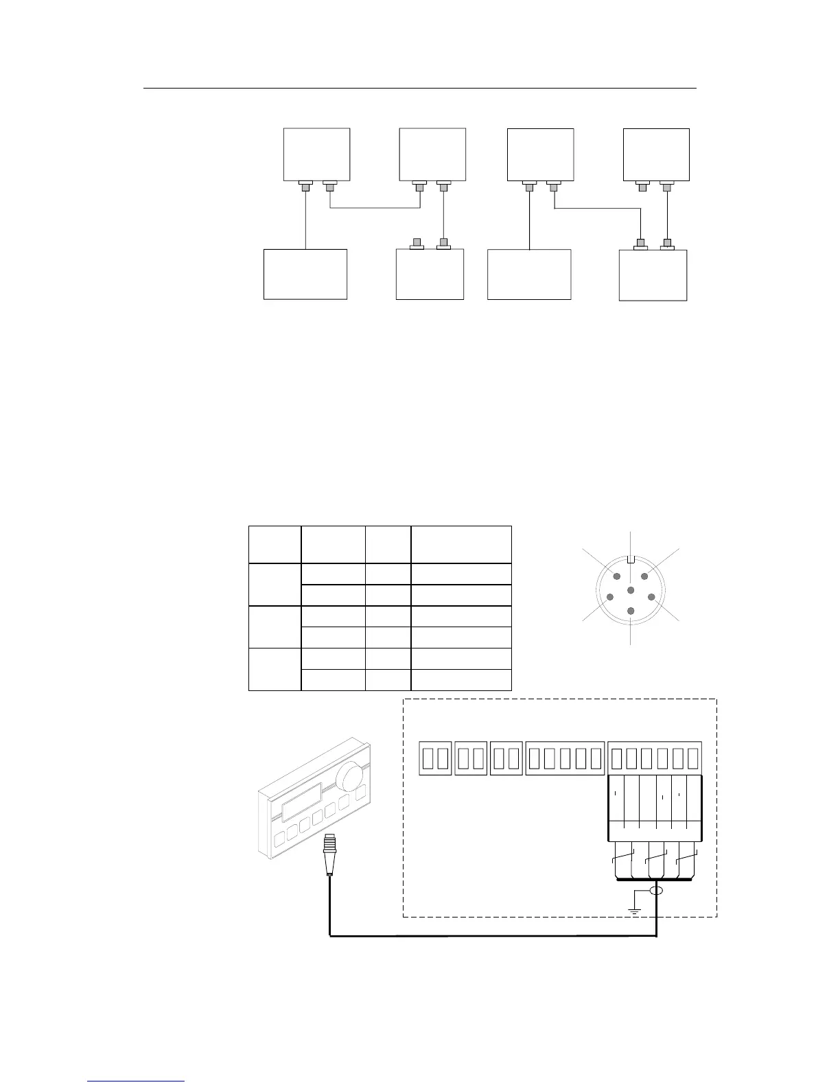
See table for pin configuration and color code of the network cable. DO
NOT MIX THE PINS AND THE CABLE COLORS!
Note ! Apply a thin layer of pure vaseline on the connector threads and make sure
the connectors are properly secured to the receptacle by the coupling ring.
The connectors are weather proof according to IP56, when properly
installed. All unused Robnet plugs must be fitted with the plastic cap to keep
the connector free of dirt and moisture. A separate screw cap for the Control
unit comes as part of the installation kit.
Cable
pairs
Color
code
Pin Signal
1. pair Pink 5 V SYSTEM+
Grey 4 V SYSTEM–
2. pair Brown 1 Bus–
White 2 Bus+
3. pair Yellow 3 On - Off
Green 6 ALARM
On-Off
Vsys+
JUNCTION UNIT
MAIN PCB
ROBNET
Bus+
Vsys
Alarm
Wh
Bn Gn
Bus
Pnk Gry
Yel
AP35
CONTROL UNIT
Figure 4-13 Control unit connection
1
24
5
6
VIEWED FROM CABLE SIDE
3