Installation
22083083H 69
For detailed information, see separate CI300X Manual.
COM
STBD
PORT
ENAB
SIN
COS
GND
Vref
SIN
HI
LO
NFU
COS
MAGN. COMP
ANALOG
GYRO
MAGNETIC COMPASS
WITH CD100A COURSE
DETECTOR
FLUXGATE COMPASS
WITH SINE/COSINE
OUTPUT
DC SUPPLY
RGC10/RGC50
GYRO COMPASS
R1
R2
S1
S2
S3
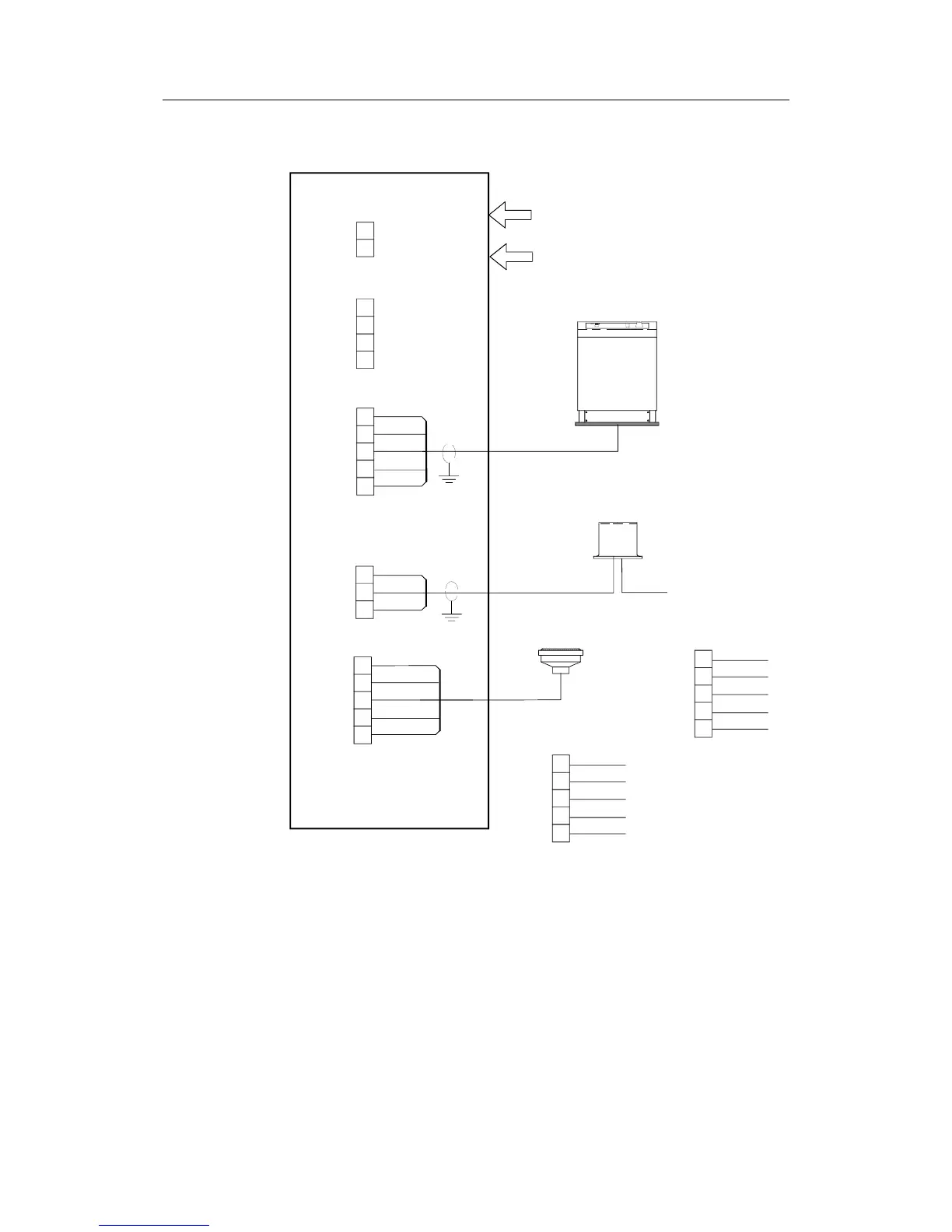
CI300X COMPASS INTERFACE
ROBNET
CONNECTIONS
TB1
TB2
TB3
TB4
TB5
ALARM
OUTPUT
(Normally open)
1
4
5
3
2
CD100 CONNECTIONS:
NON FOLLOW UP
STEERING
LEVER
ALARM
WHITE
GREY
YELLOW
GREEN
BROWN
ALT. 1
MAGN. COMP
Vref
SIN
HI
LO
COS
To identify the black wires,
measure 8-12 ohm between
orange and black* and 6-10
ohm between green and
black**.
Third black wire not in use.
ORANGE
BLUE
BLACK**
GREEN
BLACK*
ALT. 2
MAGN. COMP
Vref
SIN
HI
LO
COS
Figure 4-31 CI300X connections
Note ! CD100 has a connector that has to be cut off the cable.
4.30 CD100A Course Detector
On some installations the owner may prefer to use the boats own compass.
The compass must be fully gimballed and have a flat surface underneath to
fit the CD100A. Make hole for a 6 mm screw in the bottom of the compass
and mount the CD100A as shown on the drawing. Secure the 6 mm screw
through the centre hole of the CD100A. Make sure the cable does not
prevent the compass from moving freely in the gimbals.