Installation
22083083H 51
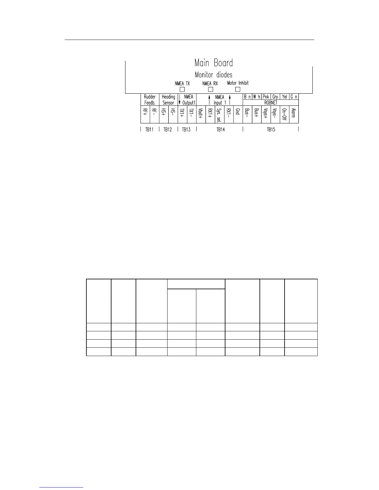
Main Board terminals
Note ! Terminal "Sys. sel." not in use.
4.9 Drive unit
The relation between drive units, drive unit voltage, input voltage, drive
output and interfacing to steering gear are shown in the table below. The
AP35 system detects whether a reversible motor or a solenoid is connected
and outputs the correct drive signal automatically.
Refer to the connecting diagram for the different drive units on page 53
onwards.
Installation instructions for the drive units are found in the manual for the
individual units.
The maximum drive current capabilities of the J3000X and J300X junction
units are different. Use the table below as reference.
HYDRAULIC PUMPS
RAM CAPACITY
MODEL MOTOR
VOLTS
JUNCTION
UNIT
MIN
cm
3
(cu. in.)
MAX
cm
3
(cu. in.)
FLOW
RATE AT 10
bar
cm
3
/min
(cu. in/min)
MAX
PRES-
SURE
bar
PWR.
CONSUMP-
TION
RPU80 12V J3000X 80 (4,9) 250 (15,2) 800 (49) 50 2,5-6 A
RPU160 12V J300X 160 (9,8) 550 (33,5) 1600 (98) 60 3-10 A
RPU300 12V J300X-40 290 (17,7) 960 (58,5) 3000 (183) 60 5-25 A
RPU300 24V J300X 290 (17,7) 960 (58,5) 3000 (183) 60 2,5-12 A
Steering gear interface: Hydraulic plumbing