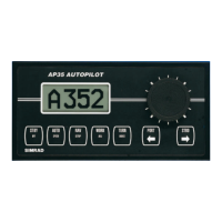
Simrad AP35 Autopilot
4 22083083H
3.1
AP35 Autopilot System .......................................................................................... 29
3.2 AP35 Control Unit.................................................................................................. 30
3.3 Junction units.......................................................................................................... 30
3.4 RFC35 Fluxgate compass ....................................................................................... 32
3.5 RC25 Rate Compass............................................................................................... 33
3.6 CDI35 Course Detector Interface ........................................................................... 33
3.7 RI35 Mk2 Rudder Angle Indicator......................................................................... 34
3.8 RF300 Rudder Feedback Unit ................................................................................ 35
3.9 RF45X Rudder Feedback Unit ............................................................................... 36
3.10 R3000X Remote ..................................................................................................... 37
3.11 CI300X Compass Interface..................................................................................... 37
3.12 NI300X NMEA Interface ....................................................................................... 38
3.13 S35 NFU Steering Lever ........................................................................................ 38
3.14 F1/2 Remote Control .............................................................................................. 39
3.15 FU50 Steering Lever............................................................................................... 40
3.16 IP protection ........................................................................................................... 41
4 INSTALLATION ................................................................................................................. 43
4.1 General.................................................................................................................... 43
4.2 Installation checklist ............................................................................................... 43
4.3 Unpacking and handling......................................................................................... 44
4.4 Determine system configuration............................................................................. 44
4.5 AP35 System Layout .............................................................................................. 45
4.6 RF300 Rudder feedback ......................................................................................... 45
4.7 RF45X Rudder Feedback Unit ............................................................................... 47
Electrical connection .............................................................................................. 48
4.8 Junction unit ........................................................................................................... 49
Cable connections................................................................................................... 49
Grounding and RFI................................................................................................. 50
Junction unit terminals............................................................................................ 50
4.9 Drive unit................................................................................................................ 51
Connecting a reversible pump ................................................................................ 53
Connecting a hydraulic linear drive........................................................................ 53
Connecting a solenoid valve................................................................................... 54
4.10 Control unit............................................................................................................. 54
Panel mounting ....................................................................................................... 54
Bracket mounting ................................................................................................... 54
ROBNET network cables ....................................................................................... 55
4.11 RFC35 Fluxgate Compass ...................................................................................... 57
4.12 RC25 Rate Compass............................................................................................... 58
4.13 R3000X Remote Control ........................................................................................ 59
4.14 FU50 Steering Lever............................................................................................... 59
4.15 S35 NFU Steering Lever ........................................................................................ 60
4.16 F1/2 Remote Control .............................................................................................. 60
4.17 RI35 Mk2 Rudder Angle Indicator......................................................................... 61
RI35 Mk2 illumination ........................................................................................... 61

 Loading...