REPAIR PROCEDURES
TB24 Plus&26J Plus Maintenance Manual 6-13 © Jun 2022
NO. DESCRIPTION
7 Bearing
8 Retainer Ring for Shaft
9 Spacer Bush
10 Retainer Ring for Hole
11 Bearing
12 Bearing Seat
13 Oil Seal
14 Output Spline Shaft
Removal of slewing drive device
1. Tag, disconnect and plug the hydraulic hoses of
slewing buffer valve and slewing reducer brake.
2. Remove the bolt and washer from the slewing
buffer valve, and then remove the slewing buffer
valve from the slewing motor.
3. Remove the bolts securing the slewing reducer to
the turntable, and then remove the slewing reducer.
Installation of slewing drive device
1. Clear the foreign matters and burrs on the mounting
surface and gears of slewing reducer.
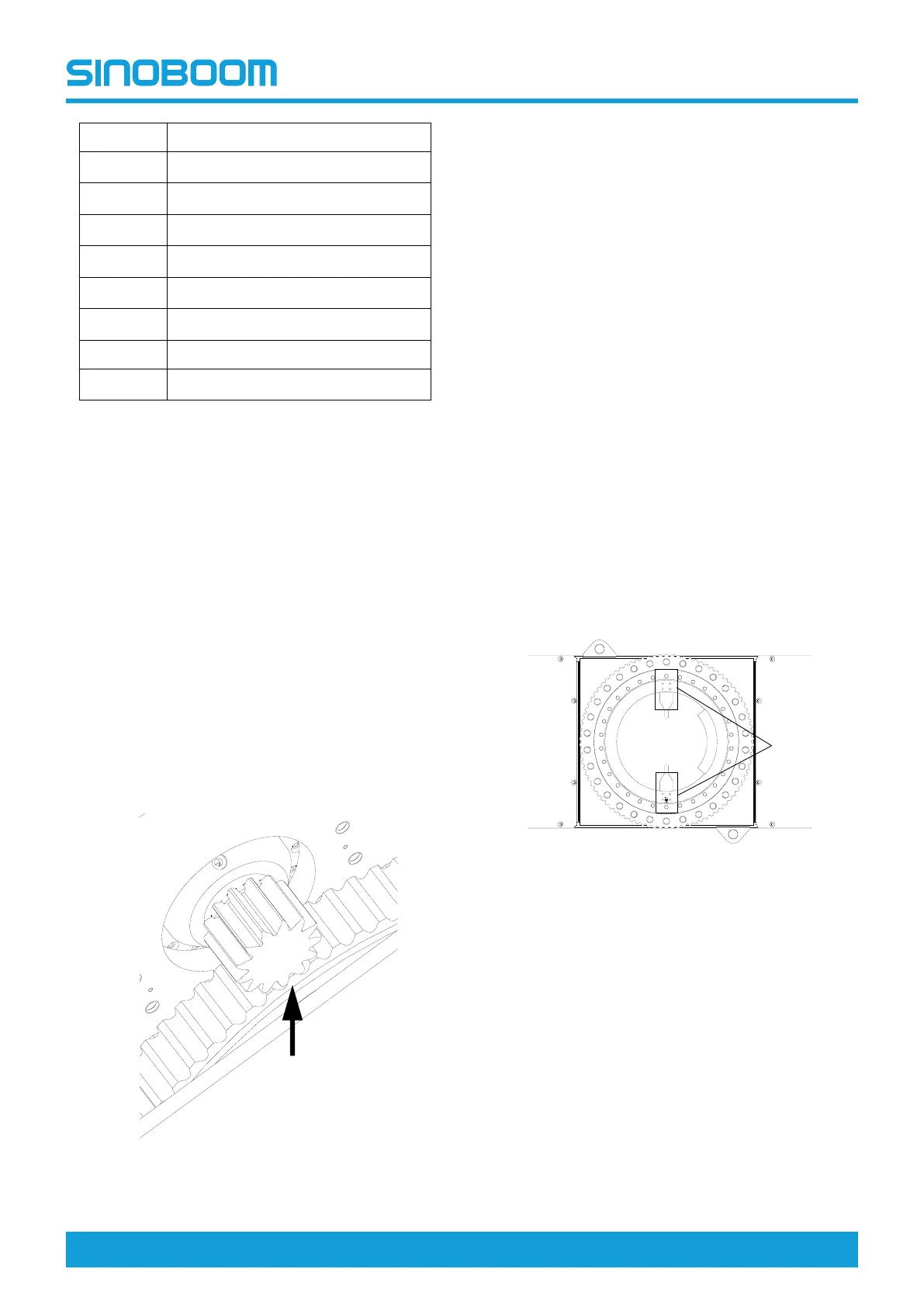
2. Place the slewing reducer on the turntable
mounting surface, use a feeler gauge to measure
the gear backlash relative to the slewing bearing,
be sure the gear backlash falls within 0.15—
0.25mm (0.006–0.01in).
Figure 6-21
3. If the gear backlash exceeds the specification,
adjust the nut to specification.
4. With washer on the bolt, apply threadlocker Loctite
272. Install the mounting bolts to secure the slewing
reducer to the turntable, after installation pre-tighten
in diagonal order.
5. Ensure the slewing reducer fits in well with the
turntable.
6. Use a wrench to tighten the bolts in diagonal order.
7. Add gear oil to the slewing reducer until the gear
surface is covered.
8. Clean the mounting surface of slewing reducer, and
mate the axis pin of slewing motor with the reducer
pin hole.
9. Rotate the motor housing to align the slewing motor
bolt hole with the reducer bolt hole. Apply
threadlocker Loctite 272 to the bolt with washer on,
install the bolt and tighten.
Installation of slewing bearing
1. Use a lifing device with sufficient capacity to lift the
slewing bearing over the mounting surface of
chassis.
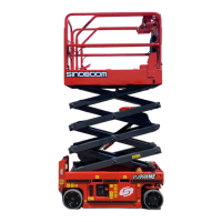
2. Ensure the soft strap intallation area of the slewing
bearing is vertical to the boom direction.
Figure 6-22
3. Use a feeler gauge to measure the clearance
between the mounting surface of the slewing
bearing and that of the chassis, ensure the
clearance≤0.2mm (0.008in).
4. Using the special washer for the high-strength bolt,
mate the washer surface with the mounting surface,
apply threadlocker Loctite 272 to the bolt, and intall
the bolts one by one.
5. Tighten the bolts in the sequence as shown in the
figure below.