REPAIR PROCEDURES
TB24 Plus&26J Plus Maintenance Manual 6-23 © Jun 2022
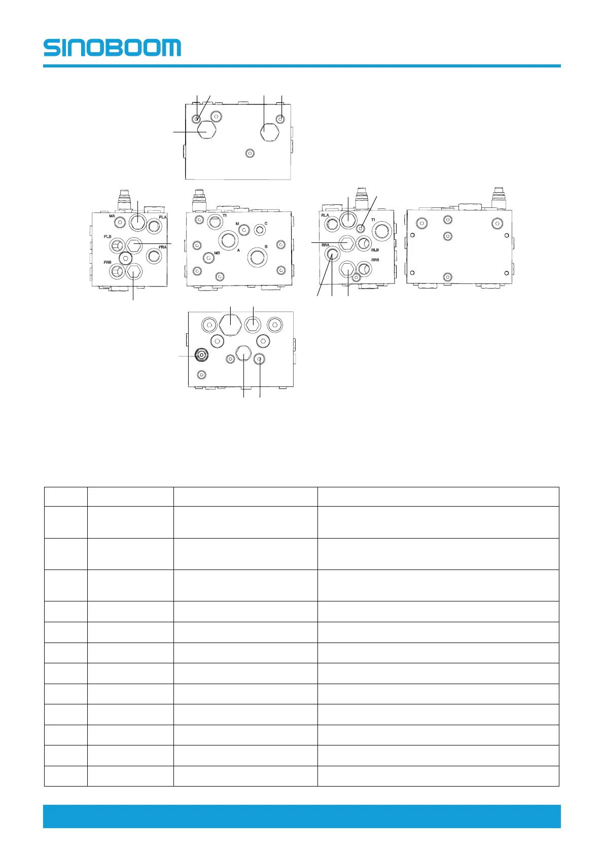
Figure 6-31 Drive control valve (PN.202040000153)
Table 6-14 Drive control valve (PN.202040000153)
NO. NAME
TORQUE
FUNCTION
1
Dividing-
combining valve
133~138Nm (98~102ft-lb)
Control flow
2–1
Dividing-
combining valve
99~104Nm (73~77ft-lb) Control the traveling flow of front wheels
2–2
Dividing-
combining valve
99~104Nm (73~77ft-lb) Control the traveling flow of rear wheels
3
Damper 5Nm (4ft-lb)
\
4
Damper 5Nm (4ft-lb)
\
5 Check valve
40~45Nm (30~33ft-lb) Keep fluid flowing in one way
6
Flushing valve 33~35Nm (24~26ft-lb) Drain the oil at the low-pressure side
7
Relief valve
40~45Nm (30~33ft-lb) Control traveling pressure
8 Shuttle valve
12~15Nm (9~11ft-lb)
Switch oil lines
9
Damper 5Nm (4ft-lb)
\
10
Damper 5Nm (4ft-lb)
\
11 Check valve
55~65Nm (41~48ft-lb) Keep fluid flowing in one way
1
2-1
2-2
3
4
4
5
5
5
5
6
7
8
9
10
15
5
15
10



 To Next Page