HRX-MM-N007
Chapter 3 Alarm Indication and Troubleshooting
HRS Series 3.3 Troubleshooting
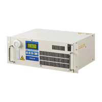
6. The dustproof filter is too dusty.
Dustproof filter on the front side of the
Thermo-Chiller or the fin of the air-cooled
condenser inside is contaminated.
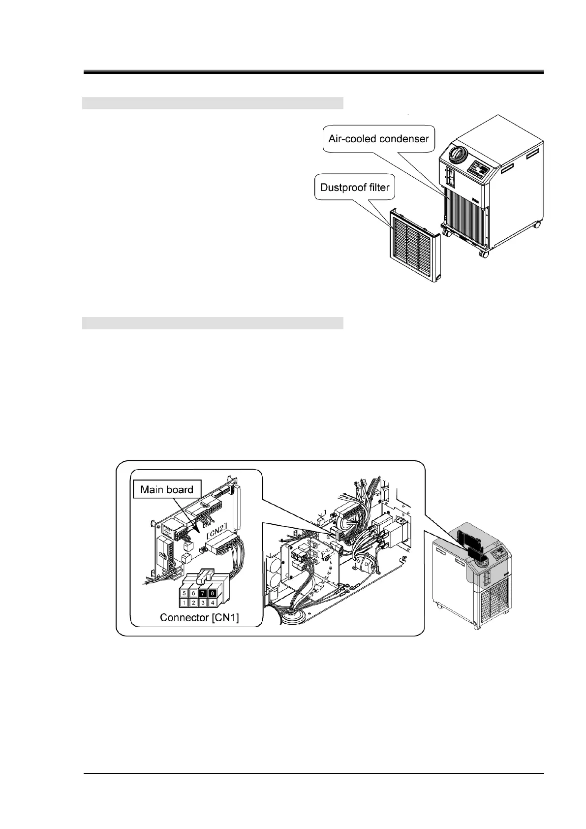
7. Check the main board.
Check that the main board outputs signals.
Disconnect the connector "CN1" on the power board.
Perform settings of the tester to make it possible to measure 24 VDC.
Contact the negative side probe to the connector pin number 7 on the cable side of the "CN1" that
has been removed, and contact the positive side probe to the pin number 8.
Operate the Thermo-Chiller (by pressing "RUN/STOP" key), and heck the voltage between the cable
connectors number 7 and number 8.
<Normal> Between pin numbers 7 and 8: 24 VDC
Fig. 3.3-62 An air-cooled condenser and
a dustproof filter
Fig. 3.3-63 Check the compressor signal
output

 Loading...