HRX-MM-N007
Chapter 3 Alarm Indication and Troubleshooting
3.3 Troubleshooting HRS Series
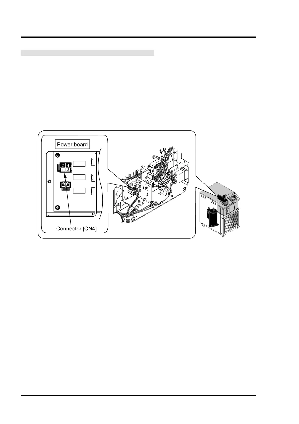
8. Check the power board.
Check that the power is being supplied to the compressor.
Disconnect the connector "CN4" of the power board to which the fan/compressor cable is
connected.
Operate the Thermo-Chiller (by pressing "RUN/STOP" key), and check if power supply voltage is
supplied to the pins number 2 to number 4 of the "CN4" connector on the power board with a tester.
[Power supply voltage to be supplied]
- -10 (100V spec.): Single phase 100 VAC (50/60Hz), or 115 VAC (60Hz)
- -20 (200V spec.): Single phase 200 VAC to 230 VAC (50/60 Hz)
Fig. 3.3-64 Check the compressor input

 Loading...