11.3.4 Yaw Test
The yaw data collection and subsequent solving for the yaw offset is usually the most difficult of the
4 tests that comprise a patch test. This is especially true if a slope is used for the yaw computation; a
feature generally works much better. The reason for this is that the area that is used for the
computation is not directly under the vessel, but in the outer beams and the slope may not be
perfectly perpendicular in relation to the course of the vessel.
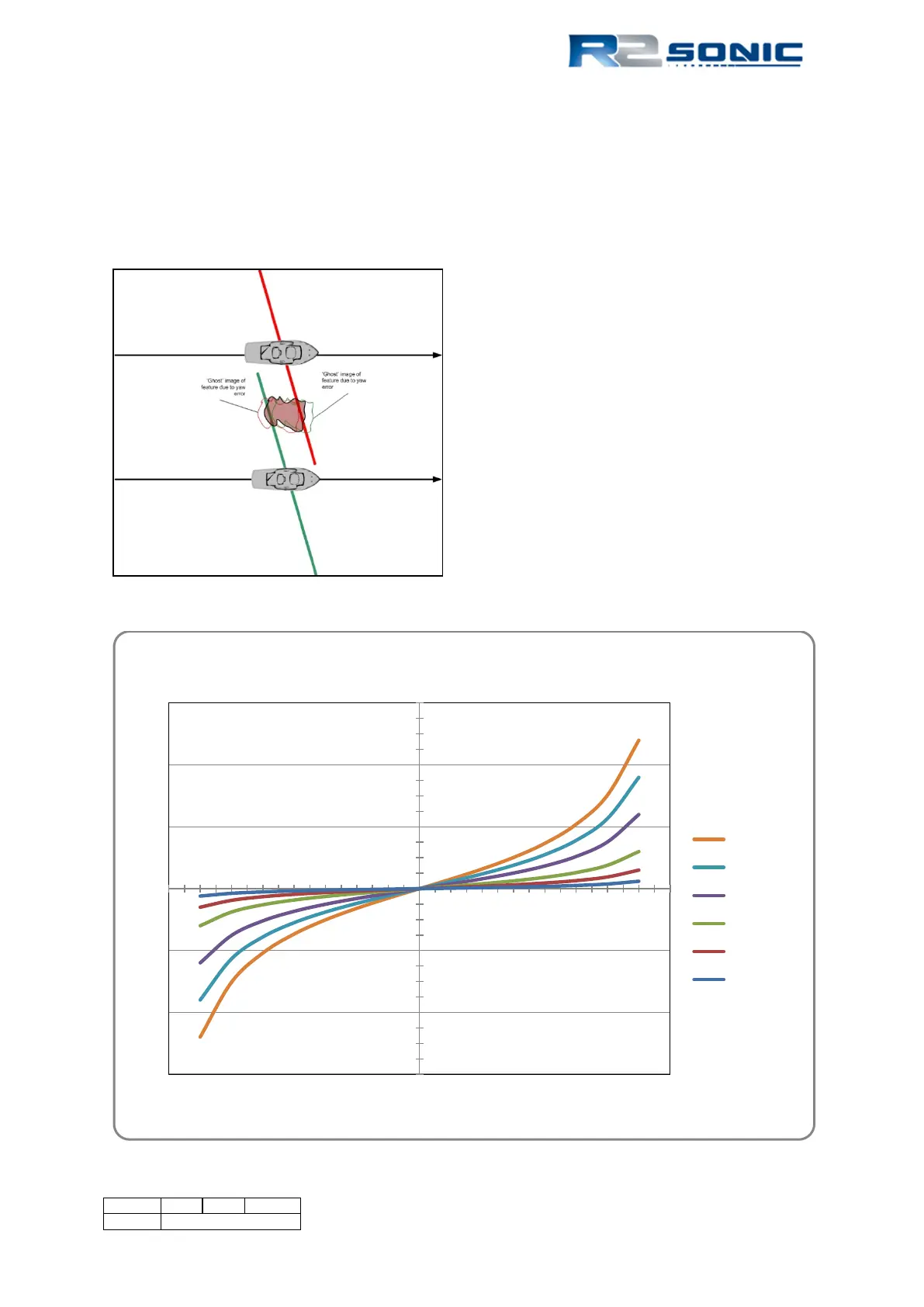
For the Yaw data collection two parallel lines are
used, with the vessel surveying in the same
direction on those lines. The lines are to be on
either side of a sea floor feature or over a slope.
The lines should be approximately 2 – 3 times
water depth in separation. A yaw error will result
in a depth position error, which increase with the
distance away from nadir.
Graph 3: Along track position error caused by 0.5° error in yaw patch test
-6
-4
-2
0
2
4
6
-80 -60 -40 -20 0 20 40 60 80
Along-track Position Error in Metres
Angle from Nadir
Position Error with a Heading Error of 0.50°
200 metres
150 metres
100metre
50 metre
25 metres
10 metres
Water Depth
Figure 135: Yaw data collection
Page 135 of 210
Version 5.0 Rev r002
Date 05-08-2014