6.4 Sonic 2024/2022 Sonar Interface Module (SIM) Block Diagram
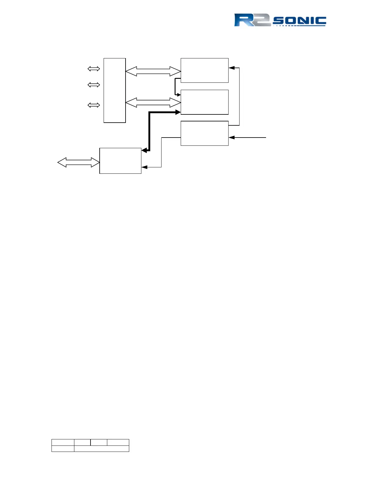
Figure 100: Sonar Interface Module Block Diagram
6.4.1 Sonar Interface Module (SIM) Block Diagram
6.4.1.1 SIM Power Requirement
The SIM operates within a voltage range of 90 to 260 VAC. The mains voltage is converted in the
various DC voltages required for the operation of the Sonic 2024/2022. Primarily, 48 VDC is sent to
the Receive Module to power the sonar head.
6.4.1.2 SIM Controller
The SIM Controller card primarily does time stamping of sensor data and deals with RS-232 and BNC
data.
6.4.1.3 SIM – Sonic Control 2000 interfacing
Sonic Control 2000 communicates with the SIM over the Gigabit Ethernet DATA RJ-45. Commands,
from Sonic Control 2000 are transmitted to the SIM and then to the Sonic 2024/2022. The Sonic
2024/2022 data passes through SIM to the data collection software.
6.4.1.4 SIM – RS-232 / Ethernet Interfacing
The SIM receives the GPS PPS and time message (NMEA ZDA), the sound velocity from the probe
near the sonar head and the motion sensor data (for roll stabilisation only). These data are routed
through the SIM Controller to the Ethernet switch for transmission to the sonar head.
Controller
Switch
Connector
Page 91 of 210
Version 5.0 Rev r002
Date 05-08-2014