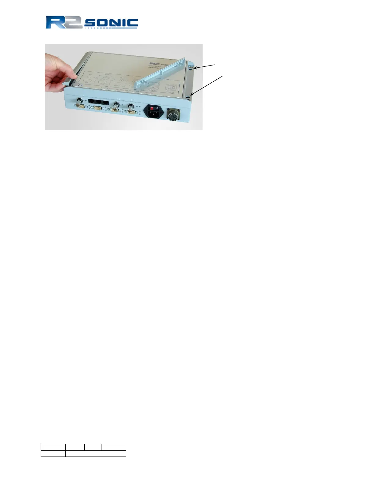
Figure 21: Removal of trim to expose securing holes
4.1.2 Electrical and Interfacing
The SIM has four DB-9 male connectors on the front. The label, on the top, clearly shows all
connections. Beginning on the left front, the connections are: GPS, Motion, Heading, and Sound
Velocity. At present time the GPS time message (for timing), sound velocity, and motion (for roll
stabilisation) inputs are enabled. Next to each DB-9 are two vertical LEDs; the top LED responds to
the input data: Green – receiving data that is being decoded; Red – no connection; Orange –
receiving data that cannot be decoded (wrong baud rate or format setting in the Sonic Control
Sensor Settings menu). There is also a LED next to the on/off rocker switch, which is the head
connection indicator: Green – head on, Red – head power off or not connected, Orange – problems
with communications or if the sonar head current draw is below expected limits.
On the second row up are three BNC connections as well as three Ethernet connections. The BNC,
which is above the GPS DB-9, receives the one Pulse Per Second (PPS) from the GPS receiver. The
PPS, along with the GPS time information on the DB-9, is used to time stamp and synchronise all
data.
The two BNC connections, to the right of the Ethernet connectors, are used to receive and send
synchronisation triggers to and from other systems.
Mains voltage (90 – 260VAC) is input via the IEC connector. Above the connector is a rocker switch
which turns on the system.
The SIM outputs the bathymetry data (from the sonar head), via the Ethernet, on the Ethernet
connection marked DATA (as marked on the label on top of the SIM). All of the RJ45 Ethernet
connections are routed to the SIM’s internal Gigabit Ethernet switch.
Page 34 of 210
Version 5.0 Rev r002
Date 05-08-2014
Part No. 96000001