7.3 Installation
7.3.1 The IMU and GPS antennas
The IMU (Inertial Measurement Unit) housing should be secured by 4 M8 (5/16” in Imperial units)
screws. The IMU housing is depth rated to 15m. The IMU can be mounted close to or on the
Multibeam transducer itself. It is not necessary to mount the IMU at the vessel’s CoG (centre of
gravity), but if it is not mounted on the CoG, it is vitally important that very accurate IMU to CoG
offsets are input into POSView.
The GNSS antennas should be mounted rigidly with respect to each other as well as the IMU, with a
separation of at least 1m between the GPS antennas. The antennas should be mounted so that they
have a clear view of the sky.
The standard cables provided with the INS option are:
1x15m IMU cable
1xBNC jumper cable
2x8m GPS antenna cables
7.3.2 INS BNC – TNC Connections
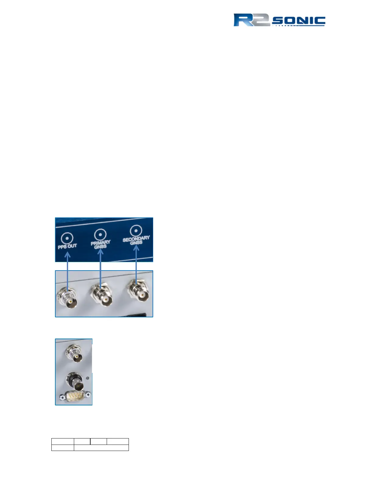
Figure 105: INS BNC & TNC Connections
Figure 106: PPS Out - PPS In
There is one BNC connection for the
PPS out. The TNC connection next to it
is for the Primary Antenna. The
Secondary antenna connects to the
TNC connection on the end.
The PPS Out is connected to the SIM PPS In, with a short
length of cable
Page 95 of 210
Version 5.0 Rev r002
Date 05-08-2014