13.6 SIM Installation – AUV
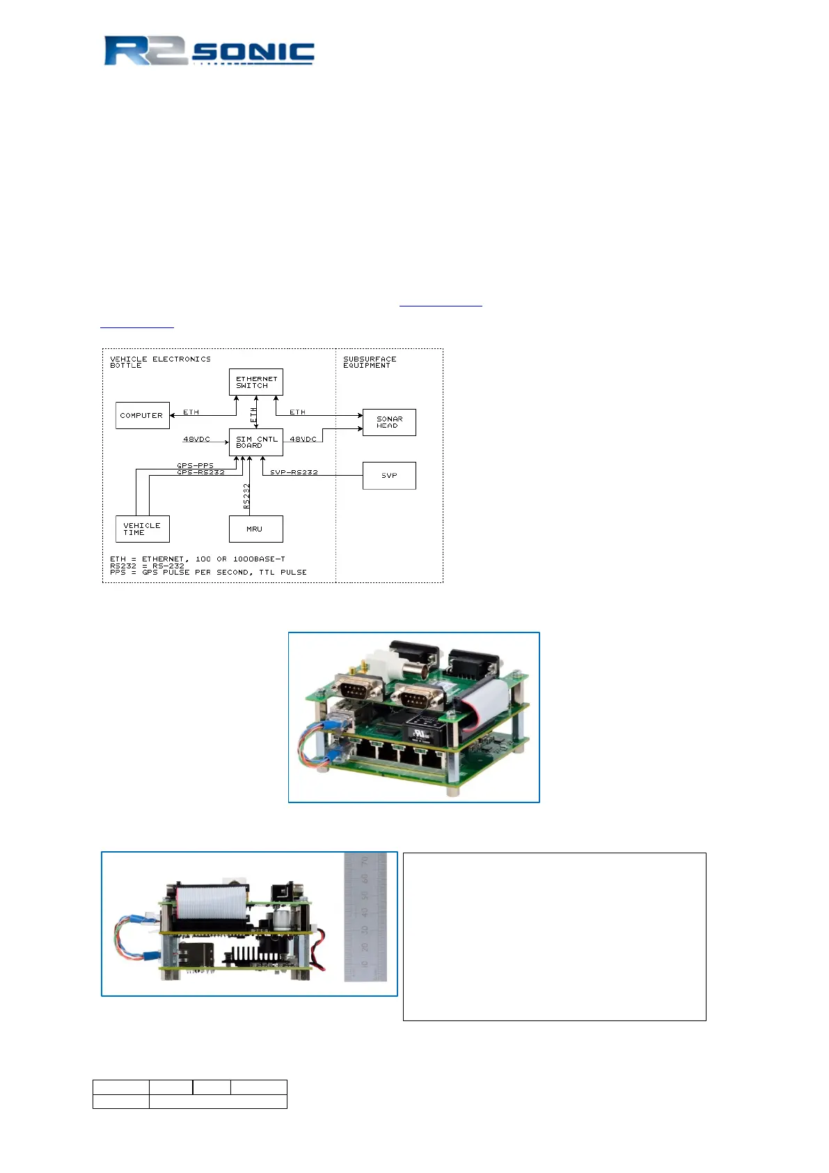
The circuit boards, inside the SIM, can be supplied separately as shown in Fig 133. The three boards
use a PC/104 size format, but does not use the PC/104 bus. The three boards are the I/O board
where the customer connects time, motion and sound velocity sensors; SIM Controller board; and a
gigabit Ethernet switch.
It’s best that the SIM Controller board supply power to the sonar head as the controller board has a
common mode choke for the 48 VDC power to the sonar head and the SIM Controller board can
control power to sonar head. If the customer uses their own custom data acquisition software, a list
of commands for the sonar head and SIM are in Appendix VIII
. The uplink data format is provided in
Appendix IX.
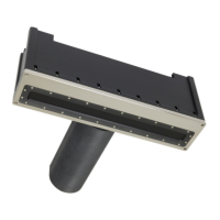
Figure 156: Typical wiring. GPS (ZDA or UTC formats) and PPS signals are supplied by the vehicle time system
Figure 157: SIM Board Stack
Figure 158: SIM Stack height
Top board: I/O
Middle board: SIM controller
Bottom board: Gigabit, 5-Port, Ethernet
switch
BNC connector: GPS PPS input
SMB connectors: sync in and out
Page 160 of 210
Version 5.0 Rev r002
Date 05-08-2014
Part No. 96000001