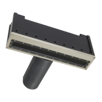
13.7 SIM Board Physical Installation
1. Power requirements: 48VDC, 50 watts average, 100 watts peak.
2. 36VDC is absolute minimum working voltage; 52VDC is absolute maximum working voltage
3. All boards are static sensitive. People handling the boards should be properly grounded.
4. User has the option to use the I/O board or not. The I/O board is connected to the SIM
Controller Board via a ribbon connector (SIM Controller J6 and I/O board J14).
5. For an AUV setup, the Ethernet connections are not used on the I/O board. The Ethernet
connections are made directly to the Ethernet Switch board.
6. If the I/O board is not used, direct connections to J6, on the SIM Controller, can be made. One
level of static protection is removed if the I/O Board is not used; however, there is enough
protection for small static events on J6.
13.8 SIM Stack LED Status Indicators
On the I/O board (top board) with nothing connected except for power:
• On power up, all the LEDs will first glow red for 0.5 second, then green for 0.5 second
• Then, they will indicate the activity level of each input.
• With no inputs, PPS, GPS, Motion, SVP LEDs will glow red.
• Trigger (sync) out will glow green.
• Heading and trigger (sync) in will be off.
• Power will be orange (red and green on) if no head is connected.
On the SIM Controller board (middle board):
• The first LED should be glowing red (not blinking). This indicates the 3.3V power supply is
working.
• The fifth LED will blink a Morse code message. This indicates that the FPGA code is running.
• All other LEDs are off.
The Gigabit switch board Ethernet Speed (bottom board):
Table 15: SIM Gigabit switch speed indicators
Page 161 of 210
Version 5.0 Rev r002
Date 05-08-2014