C-6 SPARCengine Ultra AX
i
OEM Technical Manual • May 1999
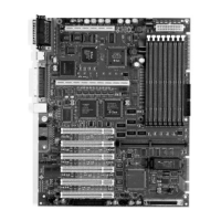
5. Install the Ultra AXi motherboard
in the chassis.
Generally all ten motherboard
mounting screws are used, although
some installations delete the screw
marked “optional”, between the PCI
connectors and the back panel.
FIGURE C-2 Ultra AXi Motherboard Installation
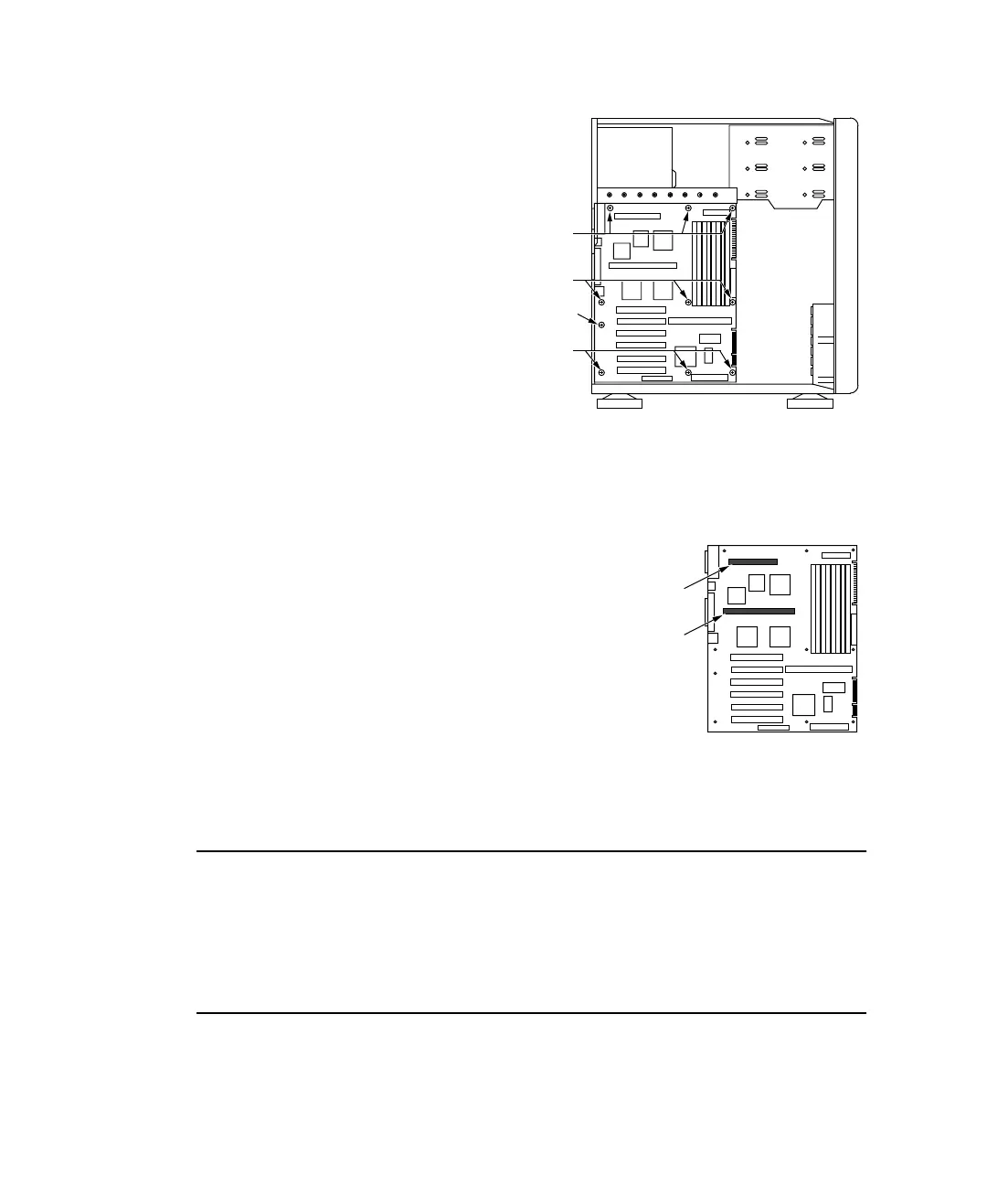
6. Install CPU Module on motherboard.
a. Position the module over the connectors making
sure all pins are aligned with the connectors and
press straight down, seating the module
(see
FIGURE C-4 on page C-7).
b. For CPU modules with pin fin heatsinks,
install the CPU hold down as shown in
FIGURE C-5 on page C-8.
c. For CPU modules with straight fin heatsinks,
install the CPU hold down with fan as shown
in
FIGURE C-6 on page C-9. Also connect the
CPU fan to J3603 (see
FIGURE C-7 on page C-10).
FIGURE C-3 UltraSPARC IIi Module
Note – When installed correctly, the CPU fan blows air toward the heatsink.
At the OBP level, the fan operates at full speed all the time.
At the Solaris level, the fan is under ASM software control and may operate at less
than full speed depending on system temperature. See Section 2.1.14.2 “Fan
Monitoring and Control” on page 2-9 for more information.
3 Screws
3 Screws
Optional
3 Screws
J0101
J0102