3-10 SPARCengine Ultra AX
i
OEM Technical Manual • May 1999
Further details regarding ASM can be found in the Sun document “SPARCengine
UltraAXi ASM Utilization and Calibration” Application Note, Part Number
(805-4877-01).
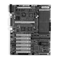
3.4.1 Temperature Monitoring Points
Temperatures are monitored at four thermistors. See FIGURE B-9 on page B-7 and
FIGURE B-13 on page B-12.
■ On the CPU module under the CPU heatsink (in all versions of CPU)
■ On the motherboard, R3407, near the mounting hole between J2002, J2001 PCI
connectors
■ On the motherboard, R3409, below the CPU module near J0101 CPU connector
■ On the motherboard, R3406, in between the CPU and Memory DIMM sockets
3.4.2 Voltage Monitoring Nodes
The ATX power supply generates a signal called Power_OK. This signal is a result of
a 'Voltage OK' condition when +3.3V and +5.0V are above 90% of their value. This is
one source of the voltage monitoring signal.
An onboard DC to DC converter generates the core voltage for the CPU: 2.6V ±5% or
1.9V ±5%, depending on the CPU module. The motherboard has circuitry to check
that this voltage is within ±10%. This is the second source of voltage monitoring
signal.
3.4.3 Fan Control and Monitoring
There are connectors to power two fans from the motherboard. The fans must be
able to operate with variable power conditions for speed control and must provide a
TTL level signal to indicate whether the fan is rotating or not. The 3-pin connectors
J3602 and J3603 are used to connect the fans. See A.2.8 on page A-7 and A.2.9 on
page A-7.
The CPU fan is required for CPU modules with straight fin heatsinks (e.g., 360 MHz,
part number 501-5148-xx; 440 MHz, part number 501-5149-xx)