Chapter 2 Specification Summary 2-13
2.2 Power Requirements
Motherboard Connector J1901
Supply Voltage +5V, +3.3V, +12V, -12V
Maximum Power (Motherboard only, no CPU installed)
Power sequencing +5V first, then +3.3V preferred, simultaneous OK.
Power Up Delay < 30ms; Slew rate: < 1V/ms.
Note – The CPU, Memory DIMMs and PCI cards are all powered through the
Motherboard. See TABLE C-2 on page C-3 for system power budgeting including
peripherals.
Note – The system can use software controlled power down. The system must be
powered up using either the front panel switch or keyboard switch. You can change
the power on/off default with the J3303 jumper (see Section 2.1.15 “Default Power
On/Off Jumper” on page 2-11 for more information).
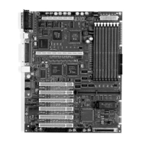
2.3 Mechanical
Board Dimension 12.0 inches (304.8 mm) x 9.6 inches (243.8 mm)
Height Restrictions 1.65 inches (41.9 mm) at the CPU Module
1.7 inches (43.2 mm) max at the IO connector stack
0.5 inches (12.7 mm) or lower for rest of the board.
The height of the DIMMs will vary with supplier.
(Ensure adequate clearance between DIMMs and the
hard disk cage)
See FIGURE B-3 on page B-3, FIGURE B-4 on page B-4
and FIGURE B-5 on page B-4.
Mounting Holes 10 holes, ATX recommendation G Profile
Voltage +3.3V +5V +12V - 12V +5V_SB
Maximum Power
1.0A 2.0A 0.5A .05A 20mA