Appendix C Assembly, Installation and Initial Start Up Procedures C-7
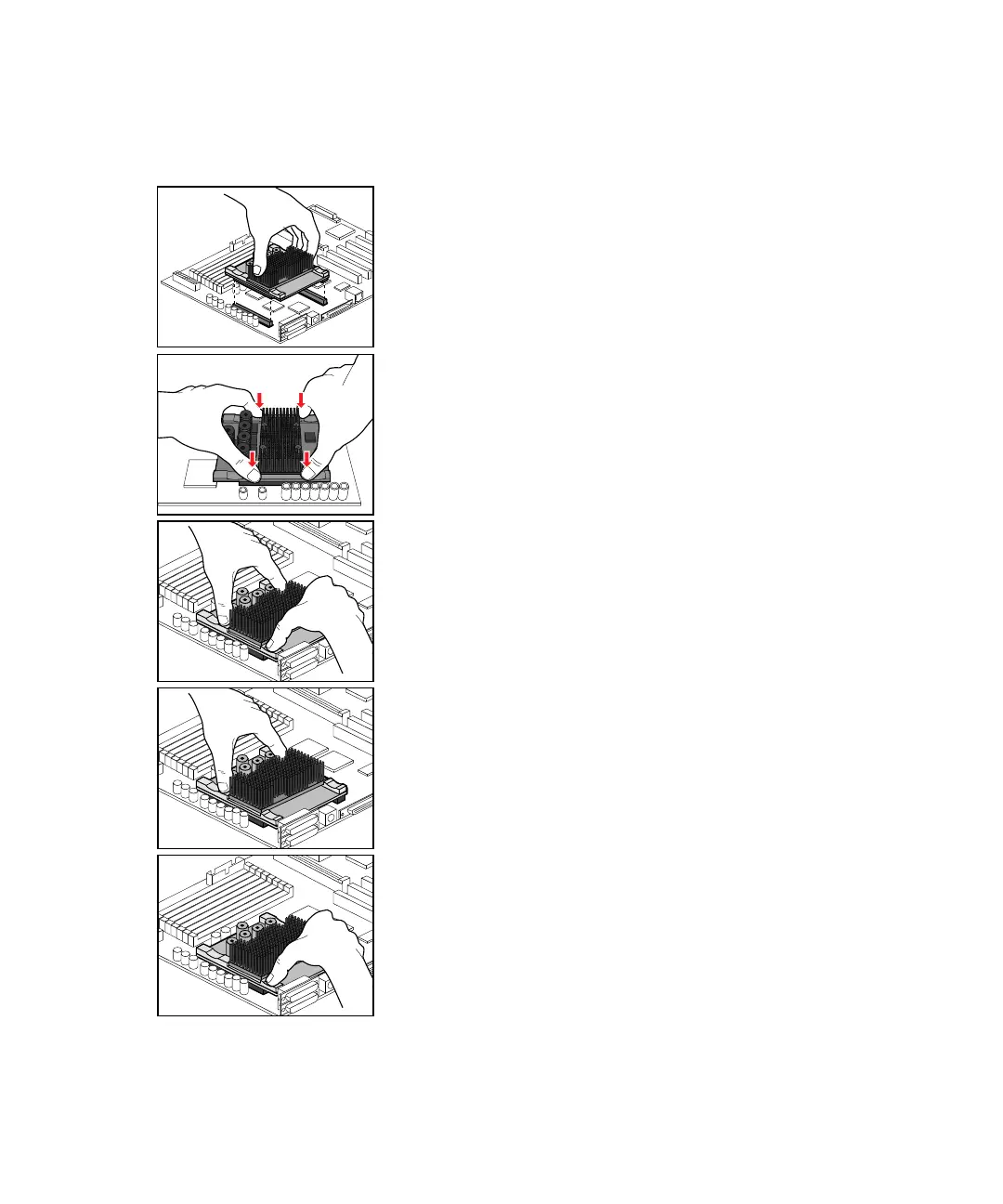
FIGURE C-4 UltraSPARC-IIi CPU Module Insertion
(module appearance varies)
2. Orient the CPU module with respect to the long and short
CPU module connectors on the Ultra AX
i
board.
Be careful to hold the CPU module only by the CPU
heatsink.
1. Place the Ultra AX
i
board on a flat and sturdy grounded surface and follow your company’s
procedure for preventing static electricity damage to sensitive electronic components.
6. Using only two fingers as shown at the base of the CPU
heatsink, push the other side of the CPU module all the
way into the CPU module connectors on the Ultra AX
i
board.
5. Using only two fingers as shown at the base of the CPU
heatsink, push one side of the CPU module all the way into
the CPU module connectors on the Ultra AX
i
board.
4. Using both hands, press lightly to mate the CPU module
with the CPU module connectors on the Ultra AX
i
board.
Be careful not to bend the ends of the CPU module.
3. Using both hands, press lightly to mate the CPU module
with the CPU module connectors on the Ultra AX
i
board.
Be careful not to bend the ends of the CPU module.