Chapter 5 Servicing Infrastructure Boards and Components 5-11
2. Remove the drives backplane.
See Section 5.3.1, “Removing the Drives Backplane” on page 5-8.
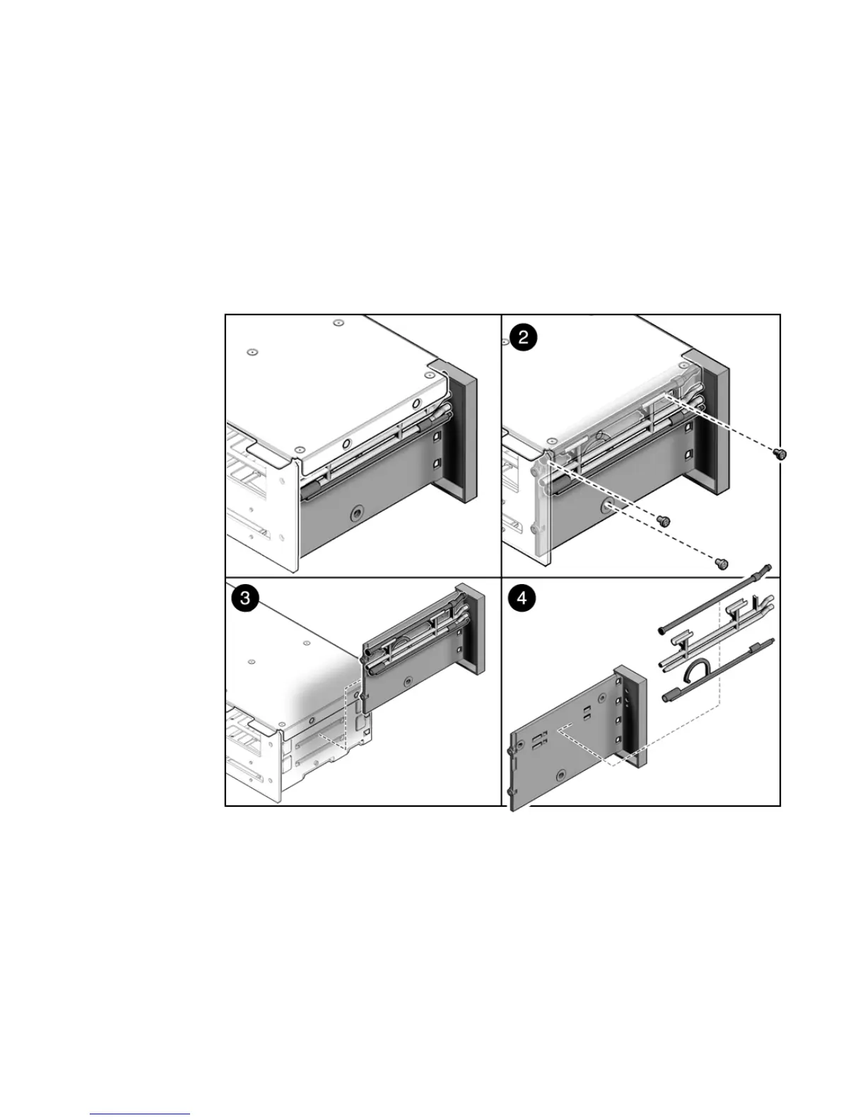
3. Remove the three No. 2 Phillips screws securing the front control panel light
pipe assembly to the drives cage. (
FIGURE 5-7)
4. Slide the light pipe assembly out of the drives cage.
FIGURE 5-7 Removing Light Pipe Assembly
5.4.2 Installing the Front Control Panel Light Pipe
Assembly
1. Align the light pipe assembly with the mounting holes on the drives cage.
2. Secure the light pipe assembly with three No. 2 Phillips screws.