Chapter 5 Servicing Infrastructure Boards and Components 5-17
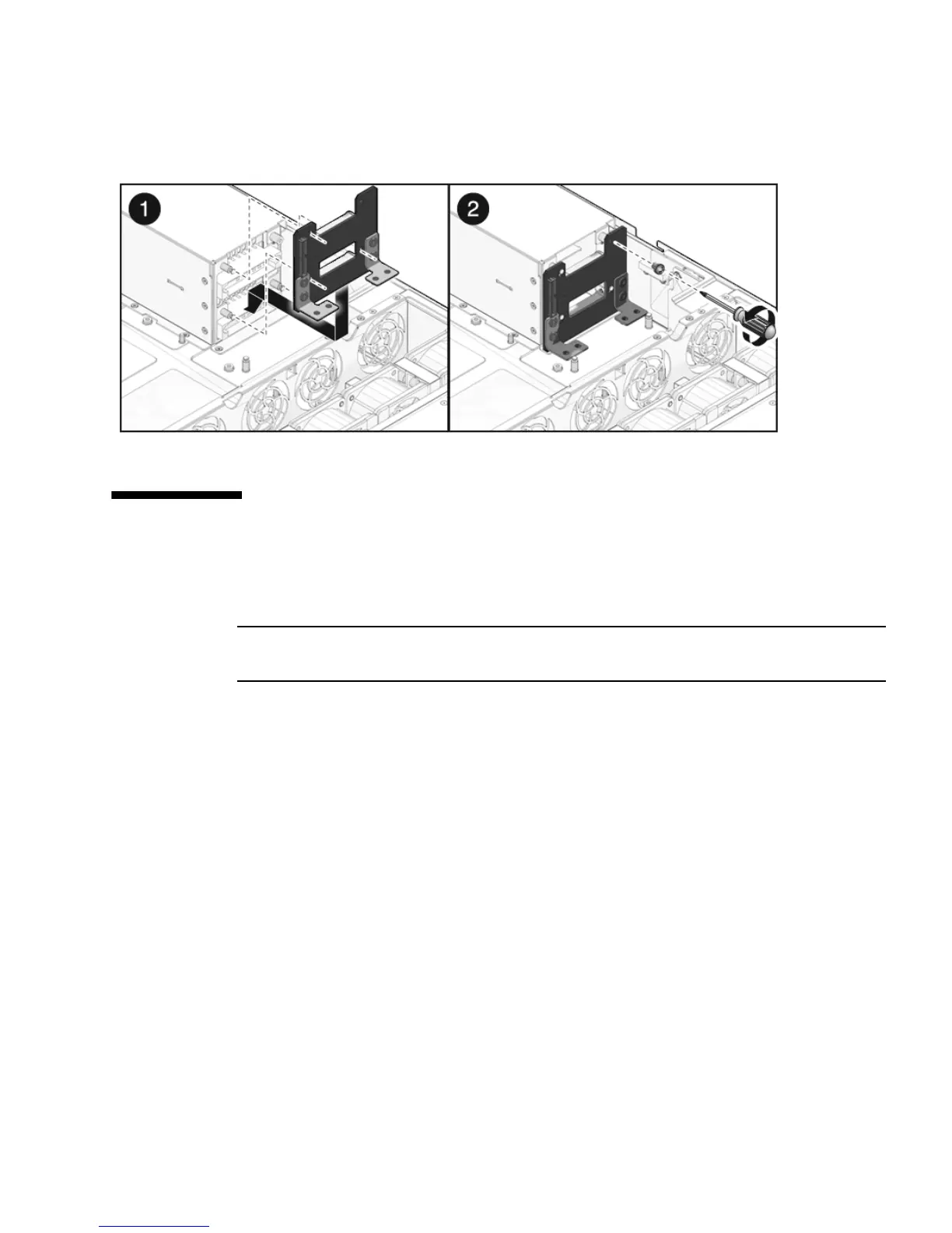
FIGURE 5-11 Installing the Power Supply Backplane
5.7 Servicing the Paddle Card
The paddle card assembly includes the top cover interlock switch.
Note – FRU: This field-replaceable unit should be replaced only by qualified service
technicians. Contact your Sun Service representative for assistance.
5.7.1 Removing the Paddle Card
1. Remove the motherboard assembly.
See Section 4.8.1, “Removing the Motherboard Assembly” on page 4-30.
2. Remove the power distribution board.
See Section 5.5.1, “Removing the Power Distribution Board” on page 5-12.
3. Remove the fan power boards.
See Section 5.1.1, “Removing a Fan Power Board” on page 5-2.
4. Remove the two No. 2 Phillips screws securing the paddle card to the chassis.
(
FIGURE 5-12)
5. Slide the paddle card back, away from its connector on the drives backplane.
6. Lift the paddle card up and out of the chassis.