Chapter 4 Servicing Motherboard Components 4-5
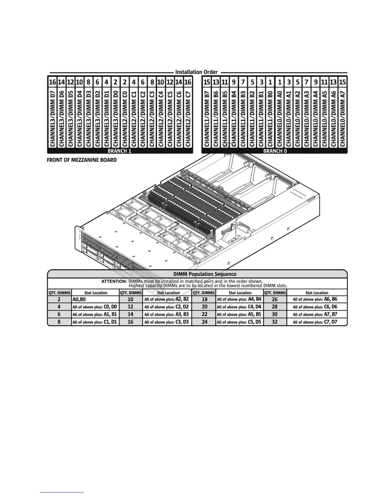
FIGURE 4-2 FB-DIMM Layout
4.1.2.1 FB-DIMM Placement
Refer to the service label on the cover for FB-DIMM placement information.
Start with Branch 0 (Channels A/B), then Branch 1 (Channels C/D).
Populate by Pair (A0/B0 then C0/D0, then A1/B1,...) of identical DIMMs.
Within each Channel:
■ Modules within a pair (A0/B0, C0/D0, A1/B1,...) must be identical with respect to
size, speed and organization.