5-22 Sun Fire X4450 Server Service Manual • November 2009
3. Remove the air duct.
See Section 4.4.1, “Removing the Air Duct” on page 4-17.
4. Remove the memory tray support bracket from the power supply bay wall.
5. Remove the fan modules.
See Section 3.3.4, “Removing a Fan Module” on page 3-12.
6. Remove the fan power boards.
See Section 5.1.1, “Removing a Fan Power Board” on page 5-2.
7. Thread the PB end of the cables underneath the midwall, towards the drives
backplane. (
FIGURE 5-15)
a. Connect the connector labeled PB 0, 1, 2, and 3 to the conector furthest from
the power supply.
b. Connect the connector labeled PB 4, 5, 6, and 7 to the connector nearest to the
power supply.
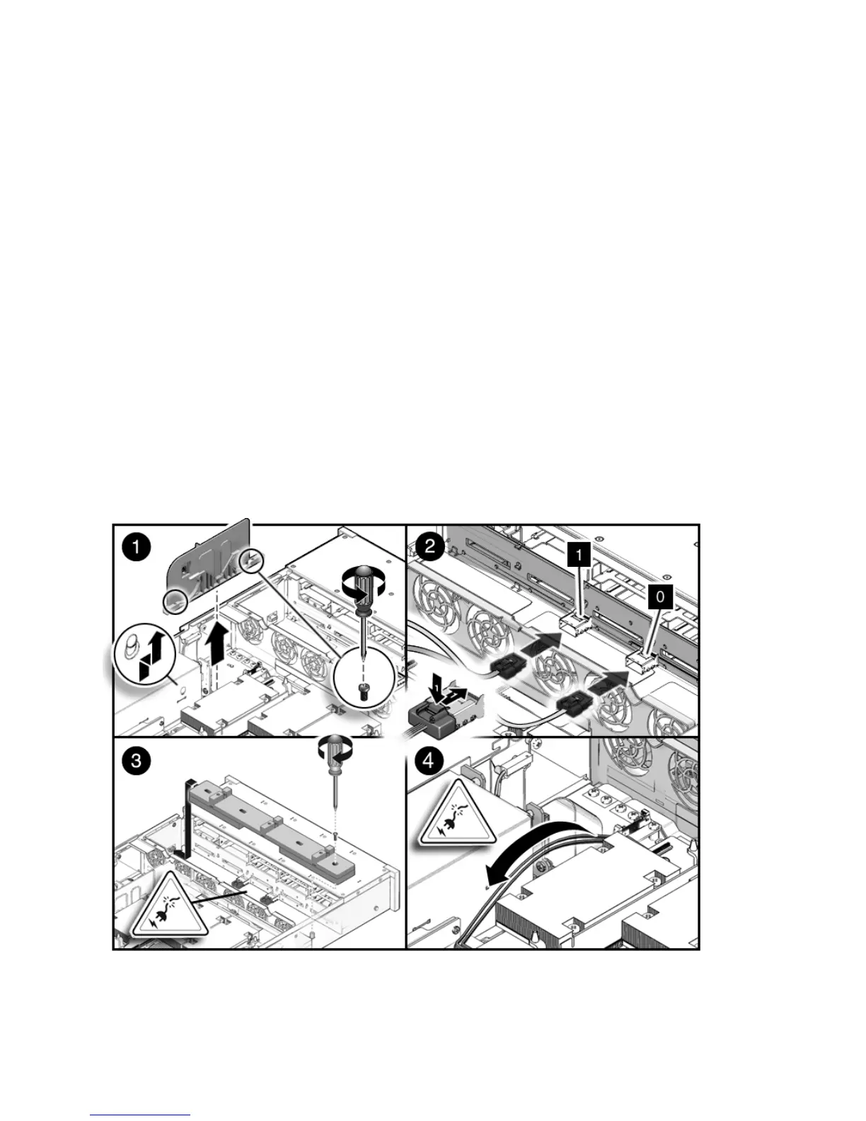
FIGURE 5-15 Installing Drive Cables in a SAS Configuration (Part 1)