Questions? Call or Text +1-801-658-0015 • 37
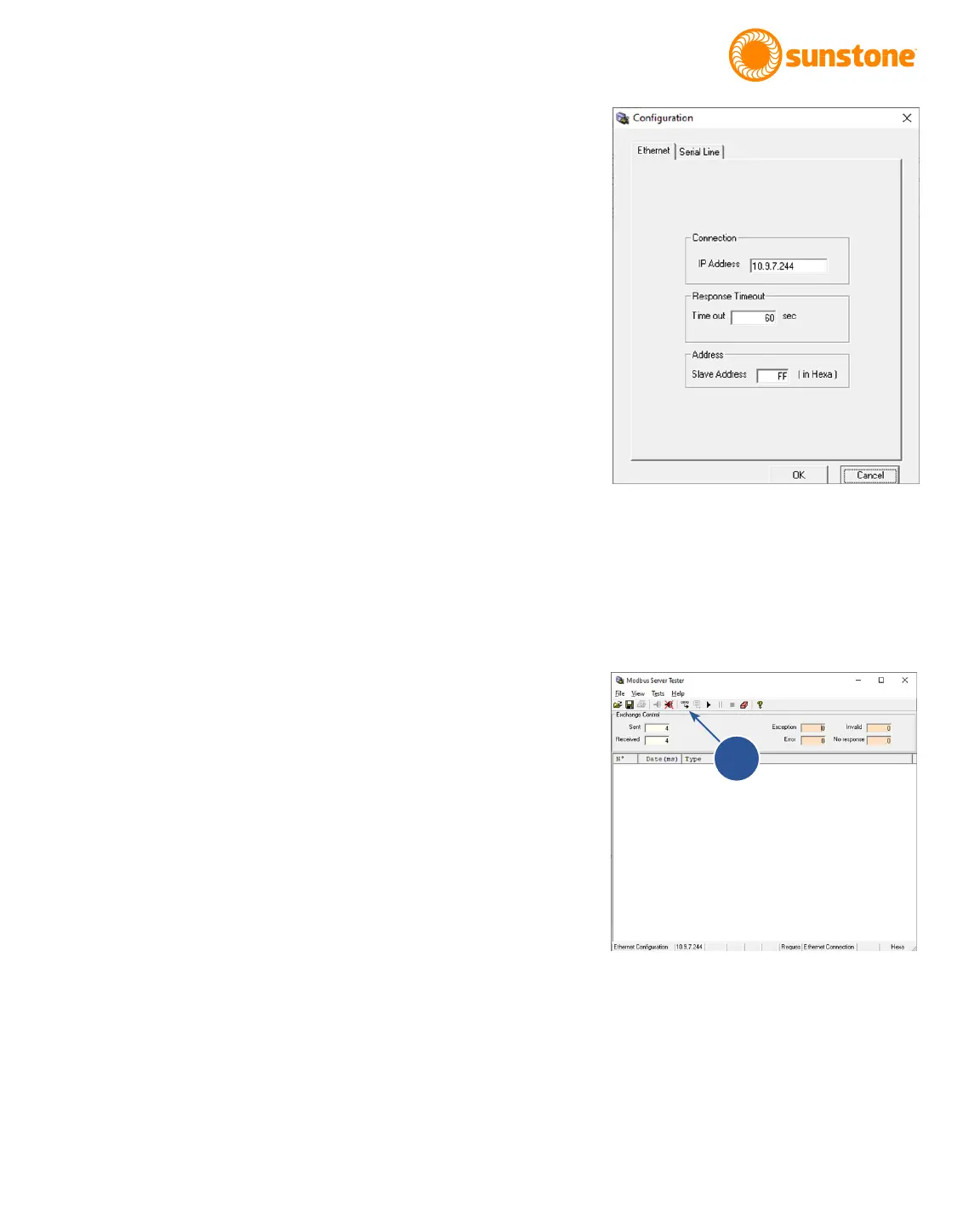
elds can be left at default: 60 second timeout and Slave
Address of “FF”. See Figure 37.1.
• Once you click OK a quick message will appear and then
close once a connection has been established. If you
encounter an error, check your network connection and
Welder IP Information and try again. You will know that you
are connected when the connection icon is greyed out and
the disconnect icon is colorful. You can also tell by going
to the le drop down menu and noticing that “Connect” is
greyed out and the “Disconnect” is not greyed out.
With conguration completed, you are now ready to commu-
nicate with the CDDP-A through Ethernet/IP using the Modbus
standards. Refer to Appendix C, Modbus Data Tables, for all
functions and commands.
Throughout these instructions, addresses and values will be
in hex format. The program inputs will appear as a decimal,
but they are a hex number. If you see “0x” before a value, it
signies that the number is hex, but the “0x” cannot be typed
into the program (Ex. a 0x0011 hex number will be written in the
program as 0011).
• To begin, click on the Send Frame icon (A) in top toolbar.
See Figure. 37.2.
• In the Send New Frame window (see Figure 38.1), keep
the default settings of “1” Times with “100” ms of Delay.
Click on the “01 Read discrete Outputs”. A new Request
Data window will appear where you can input a function
code, starting address, and quantity of outputs. See
Figure 38.2.
• Keep the function code “01”. If you look at the Modbus
Appendix C, the Read Coils Table on page 65, you will
see that the table denes what coil is pulled from the
CDDP-A when reading from coils 0 through 23. If you
choose “0000” as the starting address and “0001” as
the quantity of outputs, then you will see a reply from
the CDDP-A of the Pulse 1 Power Comparator Enable
boolean. The reply will be 1 “True” if enabled “checked”
and 0 “False” if disabled “Not checked”. Once you’re
done typing in the information click on Finish.
Figure 37.1. The Modbus Conguration screen.
Figure 37.2. Send Frame icon.
A