Questions? Call or Text +1-801-658-0015 • 19
TIMING DIAGRAMS
The following timing diagrams are included to help visualize all the dierent steps involved when making welds.
Timing diagrams for the three dierent weld head control options are included.
Fully Manual
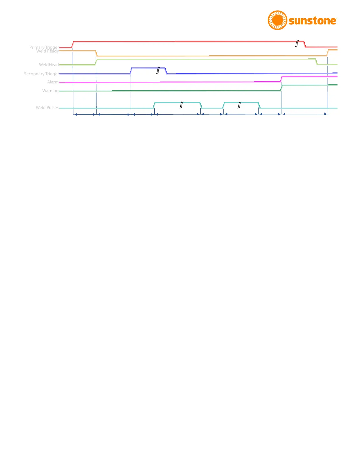
D1: A delay that occurs from the time primary trigger is triggered and the signal to the weld head is sent. Typical
time for this is between 1 and 50 milliseconds.
D2: The time between when the weld head is engaged and when trigger 2 is triggered.
D3: A delay that occurs from the time the secondary trigger is triggered, and the weld occurs. Typical time for
this is between 1 and 50 milliseconds.
Pulse 1: The duration of this delay is dependent on the energy programmed for Pulse 1, set in the Pulse Set-
tings tab on the Home Screen.
Cool: The duration of this delay is dependent on the time programmed for Delay Between Pulses. The operator
can select between 1 and 100 milliseconds, which will be ignored if either pulse is disabled. Control the cooling
duration using the Pulse Settings tab on the Home Screen.
Pulse 2: The duration of this delay is dependent on the energy programmed for Pulse 2. This is controlled on
the Pulse Settings tab on the Home Screen.
D4: After this delay, alarms and warnings are sent. Typical time for this is between 1 and 50 milliseconds.
D5: After this delay the Weld Ready signal will return to a high position. This delay will depend on the time
needed to charge to the desired energy but will typically be between 50 and 5000 milliseconds.
Figure 19.1. Sample timing diagram for Fully Manual scenario.
Primary Trigger
Weld Ready
WeldHead
Secondary Trigger
Alarm
Warning
Weld Pulses
D1
D2
D3
Pulse 1
Cool
Pulse 2
D4
D5