4-3 ELECTRICAL
7.5 – 11.5
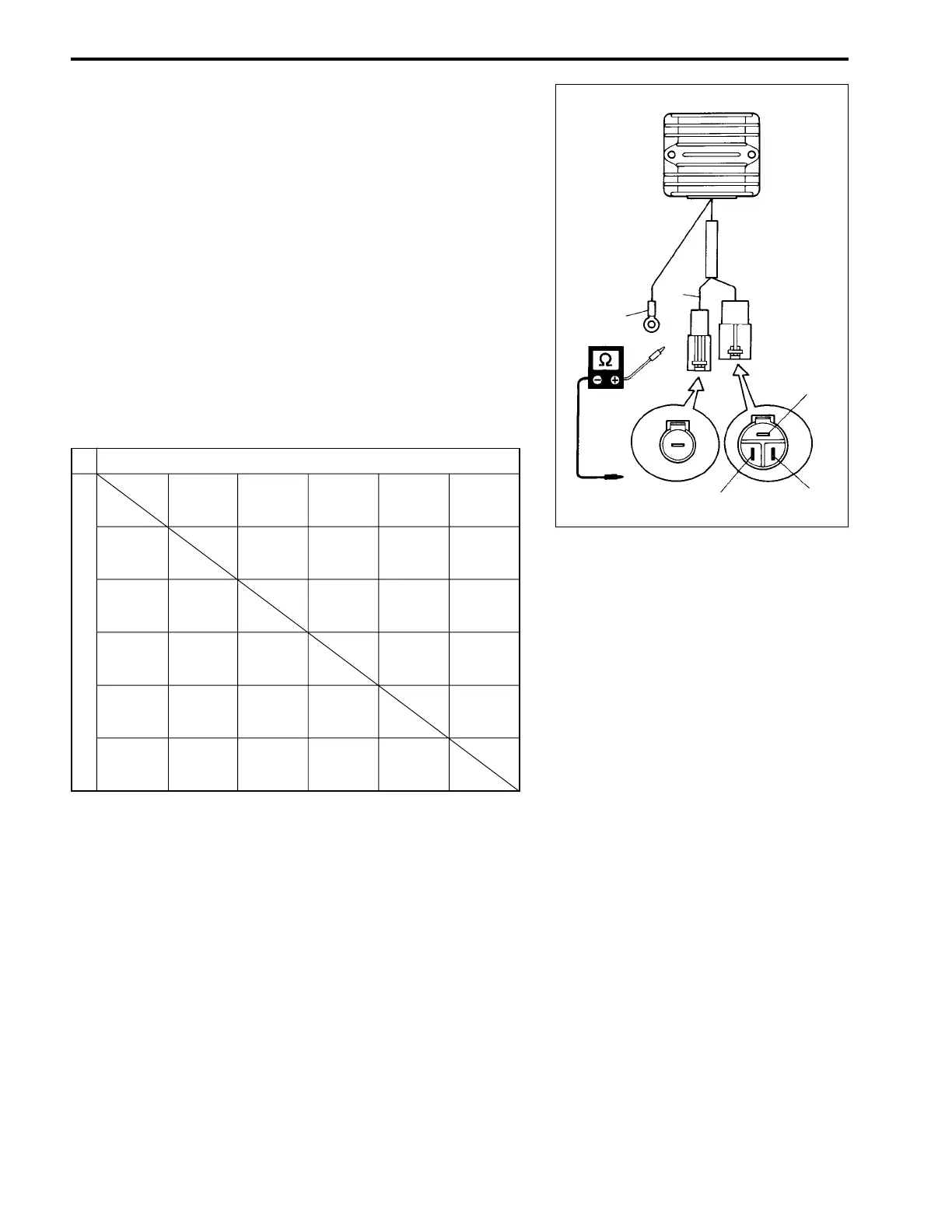
RECTIFIER & REGULATOR
09930-99320 : Digital tester
Tester range :
WW
WW
W (Resistance)
1. Disconnect all lead wires of rectifier & regulator.
2. Measure resistance between leads in the combinations
shown.
NOTE:
The values given below are for a SUZUKI digital tester.
As thyristors, diodes, etc. are used inside this rectifier & regula-
tor, the resistance values will differ when an ohmmeter other
than SUZUKI digital tester is used.
Rectifier & regulator resistance :
If measurement exceeds specification, replace rectifier & regu-
lator.
z
Tester probe
++
++
+ (Red)
Tester probe
--
--
- (Black)
Black White Yellow 1 Yellow 2 Yellow 3
Black
White
Yellow 1
Yellow 2
Yellow 3
B
W
Y
1
Y
3
Y
2
t
9 – 14
0.F
Unit : M
WW
WW
W
6 – 9
6 – 9
6 – 9
0.F
0.F
0.F
0.F
0.F
0.F
7 – 11
0.F 0.F
8 – 13
0.F 0.F
0.F
0.F
0.F : Infinity