3-35 ENGINE CONTROL SYSTEM
INSPECTION FOR RESISTANCE
09930-99320 : Digital tester
Tester range :
WW
WW
W (Resistance)
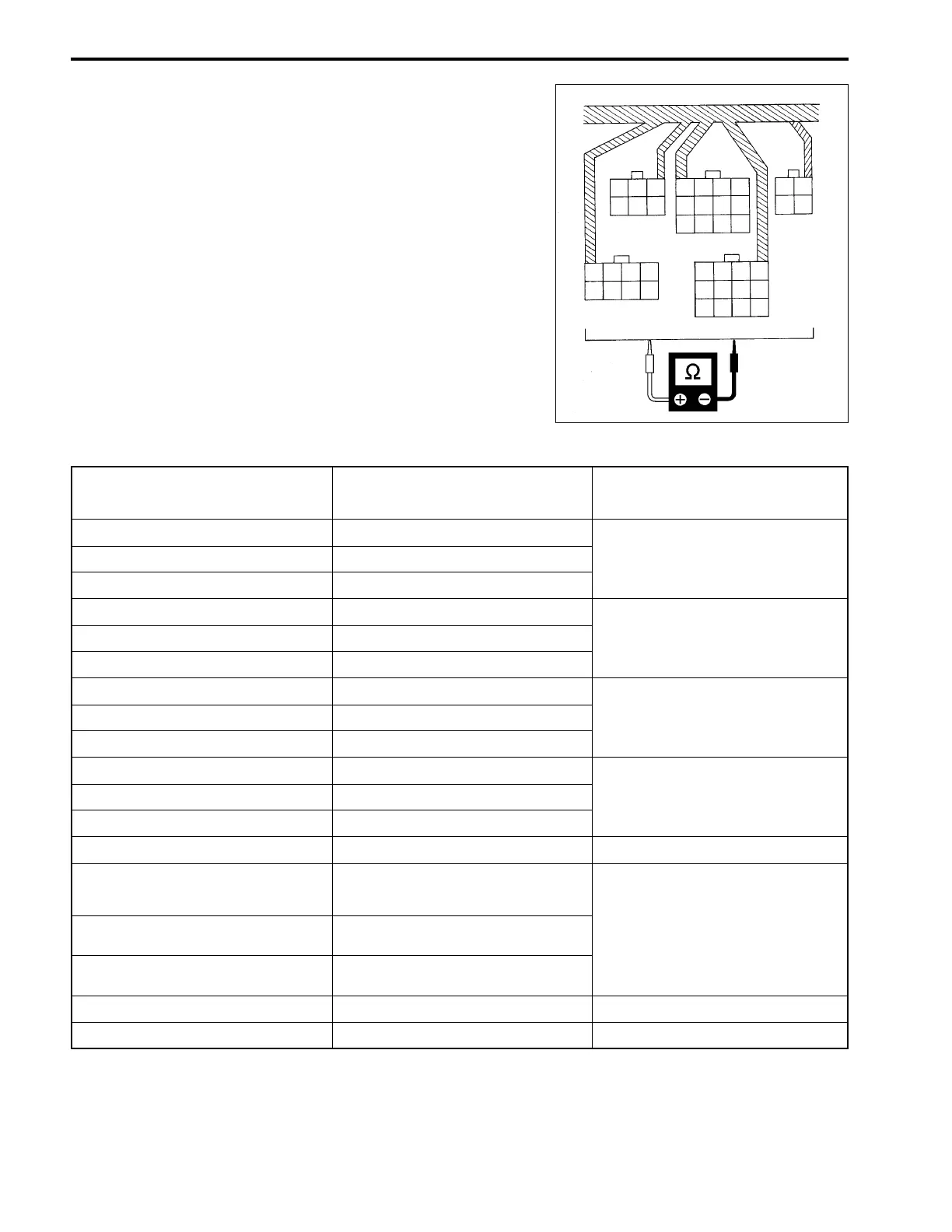
(1) Turn ignition switch OFF.
(2) Disconnect battery cables from battery.
(3) Disconnect all wires from ECM.
(4) Connect the tester probes to terminal of wire harness side,
and measure resistance according to the “RESISTANCE
TABLE”.
RESISTANCE TABLE
ITEM
TERMINAL FOR TESTER
PROBE CONNECTION
STANDARD RESISTANCE
(at 20°C)
CKP sensor No.1 E4 (R/B) to D1 (B/W)
CKP sensor No.2 E3 (W/B) to D1 (B/W)
CKP sensor No.3 E1 (R/W) to D1 (B/W)
Ignition coil No.1 (Primary) A5 (O) to B5 (Gr)
Ignition coil No.2 (Primary) A1 (Bl) to B5 (Gr)
Ignition coil No.3 (Primary) A3 (G) to B5 (Gr)
Ignition coil No.1 (Secondary) B5 (Gr) to No.1 spark plug cap
Ignition coil No.2 (Secondary) B5 (Gr) to No.2 spark plug cap
Ignition coil No.3 (Secondary)
Fuel injector No.1
Fuel injector No.2
Fuel injector No.3
IAC valve
Cylinder temperature sensor
Ex-mani. temperature sensor
C9 (V/W) to D1 (B/W)
ECM main relay B2 (P/B) to TerminalA [NOTE1]
Starter motor relay D11 (Y/G) to Ground
A4 (O/B) to B5 (Gr)
A7 (B/Y) to B5 (Gr)
B4 (B/R) to B5 (Gr)
A8 (R/W) to B5 (Gr)
B5 (Gr) to No.3 spark plug cap
D3 (Lg/W) to D1 (B/W)
D6 (Lg/B) to D1 (B/W)
168 – 252 W
1.9 – 2.5 W
8.1 – 11.1 kW
21.5 – 32.3 W
0°C ( 32°F) : 5.3 – 6.6 kW
25°C ( 77°F) : 1.8 – 2.3 kW
50°C (122°F) : 0.73 – 0.96 kW
75°C (135°F) : 0.33 – 0.45 kW
(Thermistor characteristic)
80 – 120 W
3.5 – 5.1 W
1
2
3
4
5
6
1
23
4
567
8
12
3
4
5
67
8
9
10
11
12
D (Black)
123
4
5
67
8
9
10 11
12
12
34
A
B
C (White)
E
z
t
IAT sensor
11.0 – 16.5 W