ENGINE CONTROL SYSTEM 3-26
SELF-DIAGNOSTIC SYSTEM
The self-diagnostic system alerts the operator when an ab-
normality occurs in a signal from sensor, switch, etc.
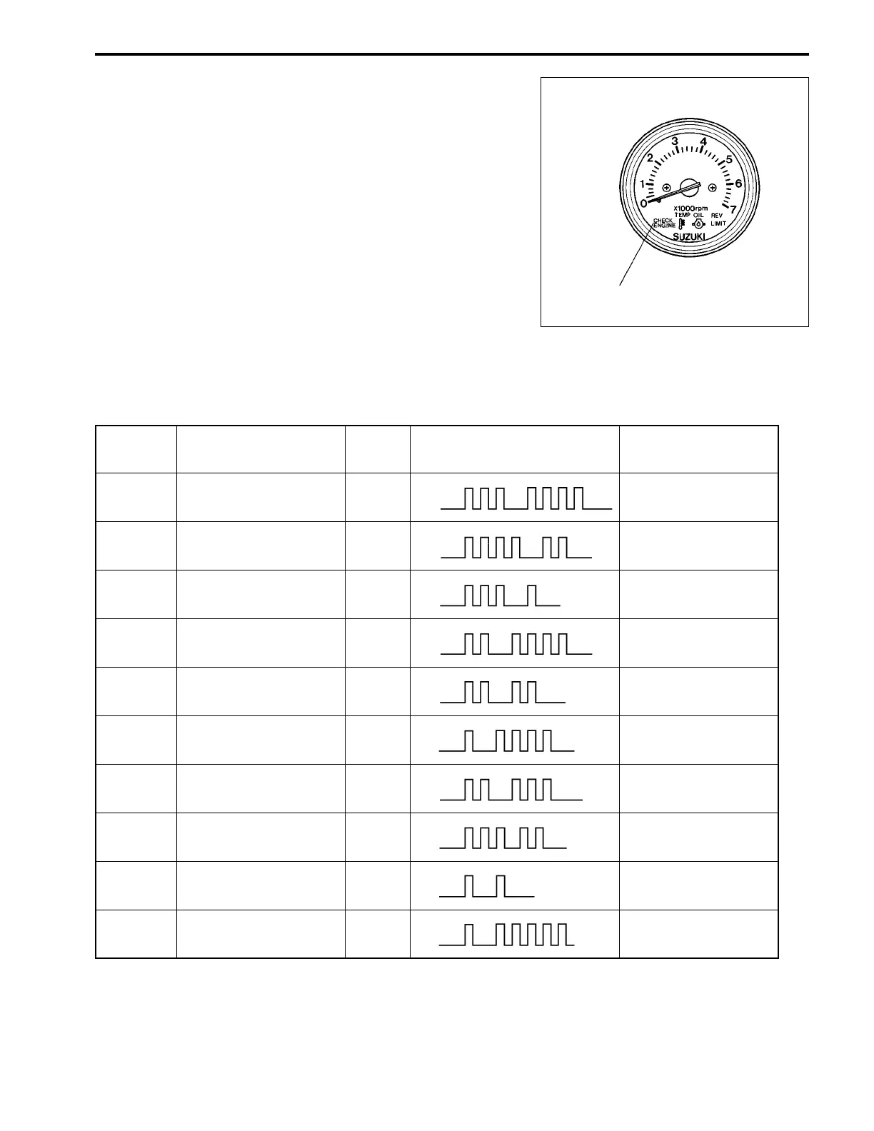
When the system is activated, the “CHECK ENGINE” lamp
flashes (lights intermittently) according to each code pattern
along with a buzzer sound.
When engine is running, the buzzer sounds a series of short
(0.2 sec.) beeps.
When engine is not running, the buzzer sounds according to
each code pattern, but not simultaneous with the lamp flash.
The buzzer sound, activated by the self-diagnostic system, can
be temporally canceled by pushing the ignition key in.
PRIORITY / CODE / PATTERN FOR SELF-DIAGNOSTIC SYSTEM OPERA-
TION
PRIORITY FAILED ITEM CODE LAMP FLASHING PATTERN
FAIL-SAFE SYSTEM
ACTIVE
1
MAP sensor 1 3 – 4
on
off
YES
2
CKP sensor 4 – 2
on
off
NO [NOTE1]
3
IAC valve/By-pass air
screw adjustment
3 – 1
on
off
NO
4
CMP sensor 2 – 4
on
off
YES
5
CTP switch 2 – 2
on
off
NO
6
Cylinder temp. sensor 1 – 4
on
off
YES
7
IAT sensor 2 – 3
on
off
YES
8
MAP sensor 2
(Sensor hose)
3 – 2
on
off
NO
9
1 – 1
on
off
NO
Rectifier & regulator
(Over-charging) [NOTE 2]
10
1 – 5
on
off
YES
Exhaust manifold
temp. sensor
MONITOR-TACHOMETER
“CHECK ENGINE” lamp