GENERAL INFORMATION 1-14
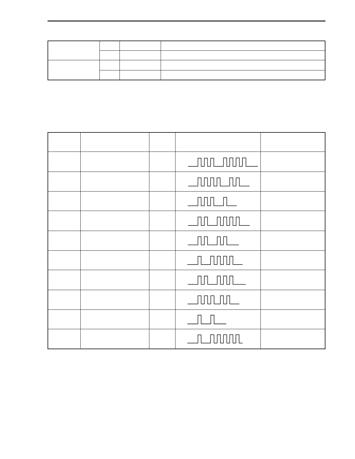
SELF-DIAGNOSTIC SYSTEM INDICATION
When the abnormality occurs in a signal from sensor, switch etc., the “CHECK ENGINE” lamp on the
monitor-tachometer flashes (lights intermittently) according to the each code pattern with buzzer sound-
ing.
PRIORITY
*
FAILED ITEM
CODE LAMP FLASHING PATTERN
FAIL-SAFE SYSTEM
ACTIVE
1
MAP sensor 1 3 – 4
on
off
YES
2
CKP sensor 4 – 2
on
off
NO
3
IAC valve/By-pass air
screw adjustment
3 – 1
on
off
NO
4
CMP sensor 2 – 4
on
off
YES
5
CTP switch 2 – 2
on
off
NO
6
Cylinder temp. sensor 1 – 4
on
off
YES
7
IAT sensor 2 – 3
on
off
YES
8
MAP sensor 2
(Sensor hose)
3 – 2
on
off
NO
9
1 – 1
on
off
NO
Rectifier & regulator
(Over-charging)
* If more than two items fail at once, the self-diagnostic indication appears according to priority order.
The indication repeats three times.
PTT MOTOR
9.8 (0.39)mm (in.)
STD
Brush length
4.8 (0.19)mm (in.)
Limit
mm (in.)STD
Commutator outside
diameter
mm (in.)
Limit
10
1 – 5
on
off
YES
Exhaust manifold temp.
sensor
22.0 (0.87)
21.0 (0.83)