3-1 ENGINE CONTROL SYSTEM
ENGINE CONTROL SYSTEM STRUCTURE
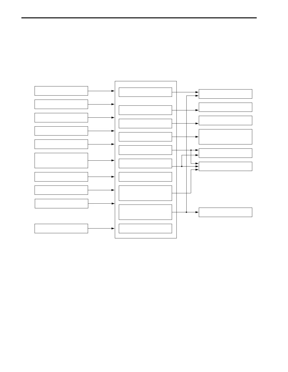
The DF40 / DF50 models employ an integrated control system which performs the control functions for fuel
injection, ignition, idle / trolling speed (idle air), etc. through the ECM (Engine control module).
SYSTEM STRUCTURE 1
[Abbreviation]
ECM (Engine control module)
CKP (Crankshaft position sensor)
CMP (Camshaft position sensor)
MAP (Manifold absolute pressure sensor)
IAT (Intake air temperature sensor)
CTP (Close throttle position switch)
IAC (Idle air control valve)
INPUT
(sensor / switch)
CONTROL
(ECM)
OUTPUT
(actuator etc.)
Fuel injection system
IAT sensor
Cylinder temp. sensor
Exhaust manifold
temp. sensor
CTP switch
Neutral switch
O
2
sensor (optional)
MAP sensor
CMP sensor
CKP sensor
Ignition system
Idle air system
Fuel pump system
Caution system
Self-diagnostic system
Fail-safe system
Operating hour
indication system
Start-in-gear protec-
tion system
O
2
feedback system
Ignition coil
IAC valve
High pressure fuel
pump
Caution buzzer
Monitor-tachometer
Fuel injector
Starter motor
Oil pressure switch